Appendix
0020188110_03 recoVAIR Installation and maintenance instructions
19
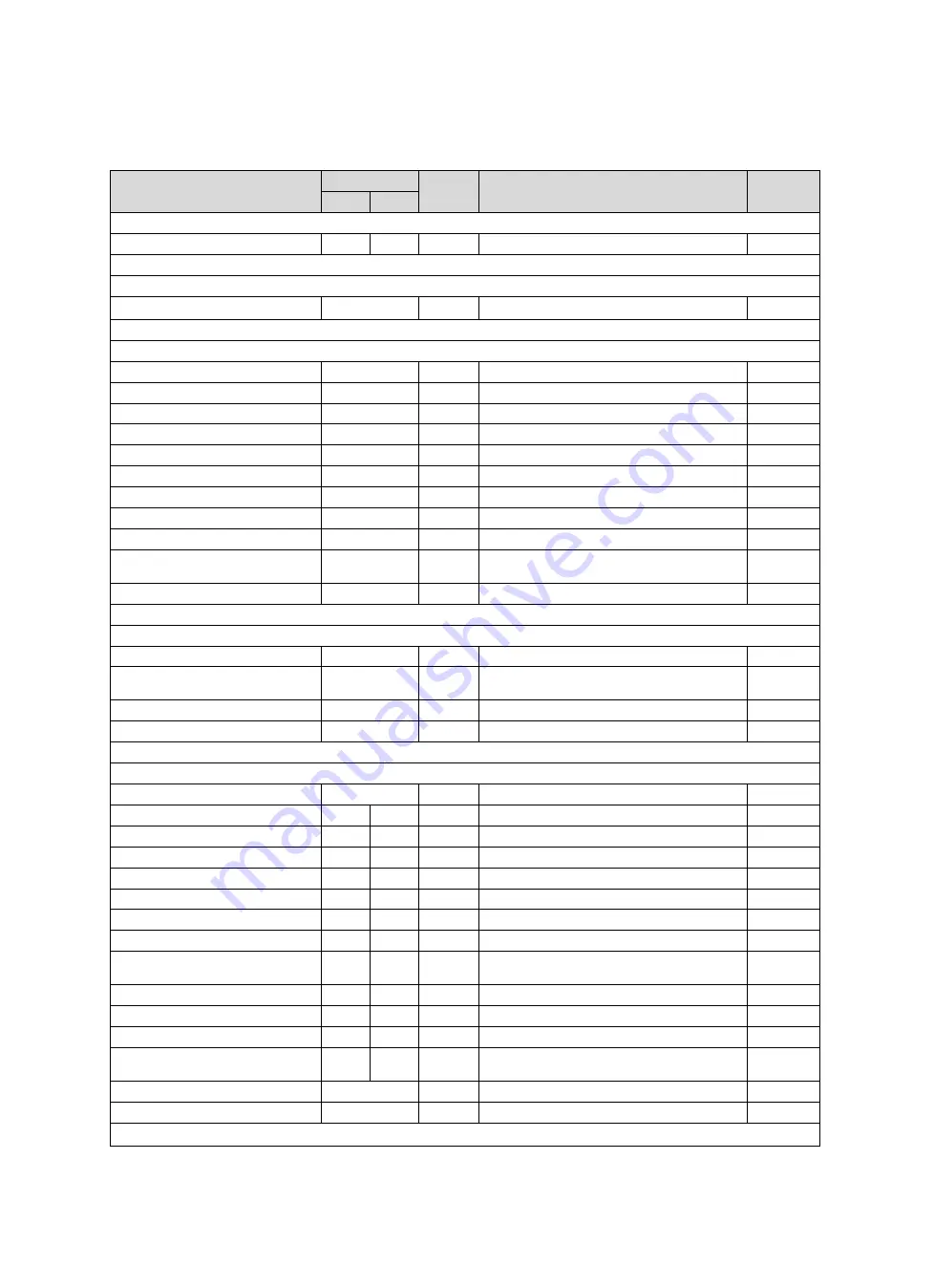
Appendix
A
Installer level
–
Overview
Setting level
Values
Unit
Increment, select
Default
setting
Min.
Max.
Installer level
→
Enter code
00
99
1 (competent person code 17)
00
Installer level
→
List of faults
→
F. XXX
–
F.XXX
1)
Delete
Installer level
→
Test menu
→
Statistics
→
Operating hours
Current value
h
Pass. cool. op. hours
Current value
h
Heat recovery hours
Current value
h
Stand. HE op. hrs
Current value
h
FPE operating hours
Current value
h
FPE operations
Current value
Exit air ventil. op. hrs
Current value
h
Sup. air ventil. op. hrs
Current value
h
Bypass steps
(if a bypass is installed)
Current value
Bypass operations
(if a bypass is
installed)
Current value
No. switch. ops
Current value
Installer level
→
Test menu
→
Check programmes
→
P.01 Bypass test
(optional)
Yes
,
No
No
P.02 Test Frost prot. element
(op-
tional)
Yes
,
No
No
P.03 Initialisation measure
Yes
,
No
No
P.04 System efficiency test
Yes
,
No
No
Installer level
→
Test menu
→
Sensor/actuator test
→
T.01 Frost prot. element
(optional)
on
,
off
off
T.03 Temperature: Outside air
−
50
60
℃
0.5
0
T.04 Temperature: Exit air
−
50
60
℃
0.5
0
T.05 Temperature: Supply air
−
50
60
℃
0.5
0
T.06 Temperature: Exhaust air
−
50
60
℃
0.5
0
T.07 Exhaust air humidity
0
100
%
0.5
0
T.08 Supply air internal target value
0
400
m
³
/h
1
0
T.10 Supply air speed
0
5000
rpm
1
0
T.11 Exhaust air internal target
value
0
400
m
³
/h
1
0
T.13 Exhaust air speed
0
5000
rpm
1
0
T.14 Air quality sensor 1
(optional)
0
5000
ppm
1
0
T.15 Air quality sensor 2
(optional)
0
5000
ppm
1
0
T.17 Position of bypass flap
(op-
tional)
0
100
%
1
0
T.18 Step switch LED
(optional)
on
,
off
off
T.19 Alarm signal
on
,
off
off
1)
Fault lists are only available, and can only be deleted, if faults have occurred.


