


Filling the heating and heat source circuit
38
Installation instructions geoTHERM 0020051574_04
6
6
Filling the heating and heat source
circuit
Before you can start operating the heat pump, the heating
circuit and the brine circuit (VWS only) must be filled.
If you use well water as the heat source (VWW only), the
heat source circuit does not have to be filled and bled
because this is an open system.
6.1
Filling regulations
Mixing additives with the heating water can result in mate-
rial damage. However, no incompatibility with Vaillant appli-
ances has been detected with proper use of the following
products over a long period.
>
Observe the manufacturer’s instructions regarding addi-
tives if you are using these.
Vaillant accepts no liability for the compatibility of any addi-
tives in the rest of the heating installation or for their effect
Additives used for cleaning
(subsequent flushing is required)
– Fernox F3
– Sentinel X 300
– Sentinel X 400
Additives intended to remain permanently
in the system
– Fernox F1
– Fernox F2
– Sentinel X 100
– Sentinel X 200
– Fernox Antifreeze Alphi 11
– Sentinel X 500
Additives for frost protection intended
to remain permanently in the system
– Fernox Antifreeze Alphi 11
– Sentinel X 500
>
Inform the operator about the measures that are
required if these additives have been used.
>
Inform the operator about the behaviour that is required
for frost protection.
>
You must comply with the applicable national regulations
and technical standards for preparing the filling and
make-up water.
Provided the national regulations and technical standards
do not make any greater demands, the following applies:
>
You must prepare the heating water,
– if the entire amount of filling and make-up water
exceeds three times the nominal capacity of the heat-
ing installation throughout the service life of the sys-
tem or
– if the limit values in the following tables are not com-
plied with.
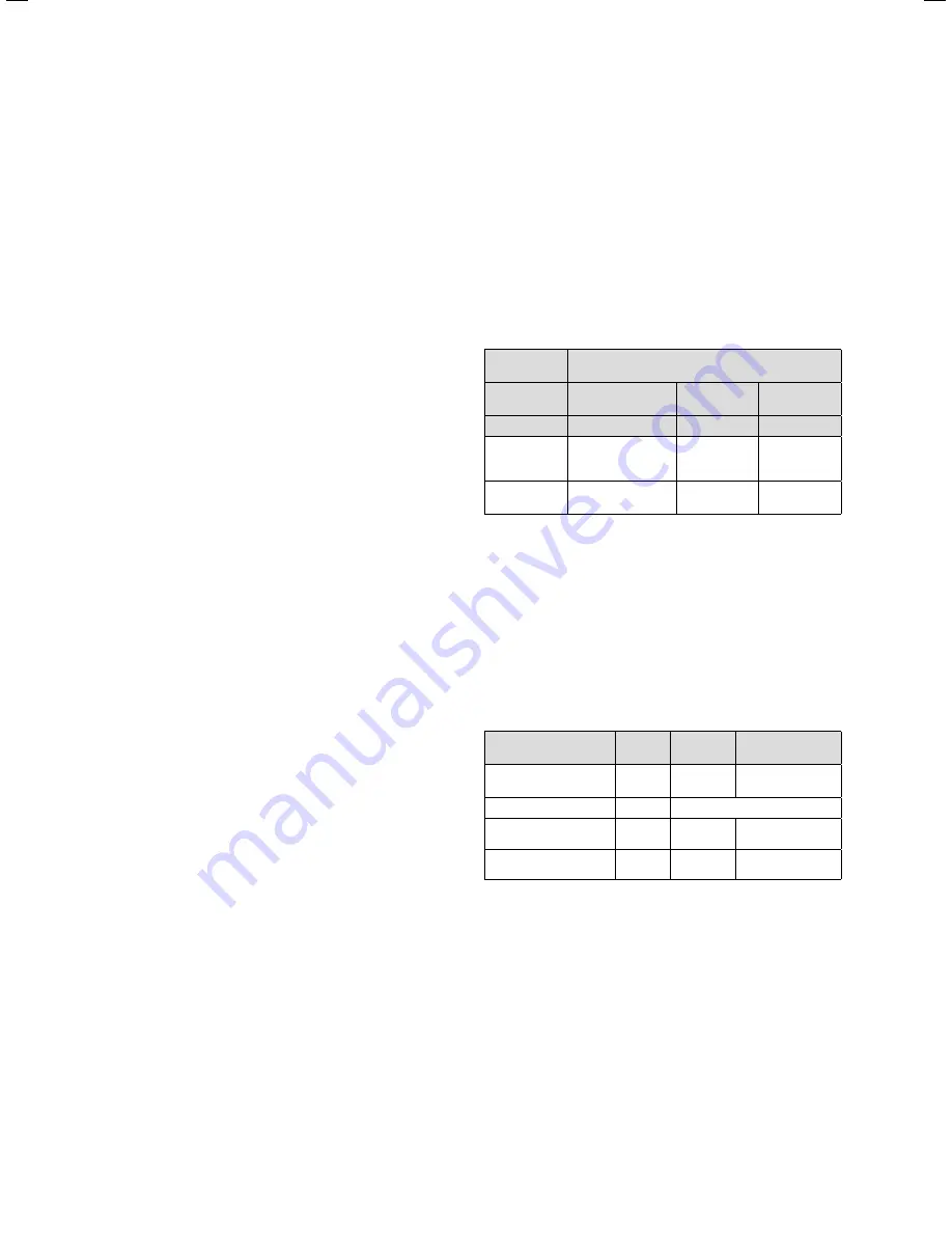
Total heat-
ing output
Overall hardness for the smallest boiler
screen surfaces
)
20 l/kW
> 20 l/kW
< 50 l/kW
> 50 l/kW
kW
mol/m
3
mol/m
3
mol/m
3
< 50
No change or < 3
1)
2
0.02
> 50 to 200
2
1.5
0.02
1) on systems with circulation water heaters and for systems
with electric heating elements
2) from the specific system volume (nominal capacity in litres/
heating output; the lowest heating output must be used for
multiple boiler installations). These specifications only apply
up to three times the system volume for filling and make-up
water. If three times the system volume is exceeded, the
water must be treated in accordance with the specifications
from the VDI (softening, desalting, hardness stabilisation or
blowing down). This is exactly the same as if the limit values
in Table 6.1 were exceeded.
6.1 Guide values for the heating water: water hardness
Heating water
characteristics
Unit
Low-salt
Saline
Electrical conductivity
at 25 °C
m
S/cm
< 100
100 - 1500
Appearance
free of sedimentary materials
pH value at 25 °C
8.2 - 10.0
1)
8.2 - 10.0
1)
Oxygen
mg/l
< 0.1
< 0.02
1) For aluminium and aluminium alloys, the pH range is restricted
from 6.5 to 8.5.
6.2 Guide values for the heating water: Salt content