Appendix
70
Installation and maintenance instructions flexoTHERM exclusive 0020213394_01
VWF 57/4
VWF 87/4
VWF 117/4
VWF 157/4
VWF 197/4
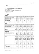
Sound power level A7/W55
EN 12102/EN 14511 L
WI
in heating mode
40.9 dB(A)
52.7 dB(A)
46.1 dB(A)
48.0 dB(A)
46.4 dB(A)
Sound power level A35/W18
EN 12102/EN 14511 L
WI
in cooling mode
48.3 dB(A)
54.7 dB(A)
49.7 dB(A)
46.8 dB(A)
47.2 dB(A)
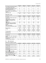
Application limits for the heat pump: Heating and cooling (heat source = air)
At the same volume flow rates in the heating circuit (
Δ
T 5K or
Δ
T 8 K) as for the nominal heat output test under standard
nominal conditions.
Operation of the pump outside the application limits results in the heat pump being switched off by the internal control and
safety devices.
VWF 57/4
VWF 87/4
VWF 117/4
VWF 157/4
VWF 197/4
Application limits for the heat pump:
Heating (Air heat source)
–
A40/W65
–
A40/W25
–
A
−
22/W25
–
A
−
22/W50
–
A
−
2/W65
–
A15/W65
–
A40/W65
–
A40/W25
–
A
−
22/W25
–
A
−
22/W50
–
A
−
2/W65
–
A15/W65
–
A40/W65
–
A40/W25
–
A
−
22/W25
–
A
−
22/W50
–
A
−
2/W65
–
A15/W65
–
A40/W65
–
A40/W25
–
A
−
22/W25
–
A
−
22/W50
–
A
−
2/W65
–
A15/W65
–
A40/W65
–
A40/W25
–
A
−
22/W25
–
A
−
22/W50
–
A
−
2/W65
–
A15/W65
Application limits for the heat pump:
Cooling (Air heat source)
–
A20/W20
–
A40/W20
–
A40/W5
–
A20/W5
–
A20/W20
–
A40/W20
–
A40/W5
–
A20/W5
–
A20/W20
–
A40/W20
–
A40/W5
–
A20/W5
–
A20/W20
–
A40/W20
–
A40/W5
–
A20/W5
–
A20/W20
–
A40/W20
–
A40/W5
–
A20/W5
P.4
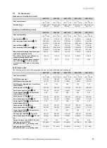
Groundwater heat source
Heat source circuit/brine circuit and groundwater circuit
VWF 57/4
VWF 87/4
VWF 117/4
VWF 157/4
VWF 197/4
Heat source module
VWW 11/4 SI
VWW 11/4 SI
VWW 11/4 SI
VWW 19/4 SI
VWW 19/4 SI
Nominal flow of groundwater at
Δ
T 3 K
with W10W35
1,450 l/h
2,240 l/h
3,520 l/h
4,540 l/h
5,480 l/h
Brine fluid type
Ethylene glycol
30% vol.
Ethylene glycol
30% vol.
Ethylene glycol
30% vol.
Ethylene glycol
30% vol.
Ethylene glycol
30% vol.
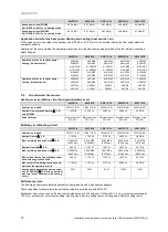
Building circuit/heating circuit
VWF 57/4
VWF 87/4
VWF 117/4
VWF 157/4
VWF 197/4
Heat source module
VWW 11/4 SI
VWW 11/4 SI
VWW 11/4 SI
VWW 19/4 SI
VWW 19/4 SI
Nominal flow at
Δ
T 5 K
1,100 l/h
1,720 l/h
2,170 l/h
2,920 l/h
3,990 l/h
Max. remaining feed head with
Δ
T 5 K
0.065 MPa
(0.650 bar)
0.042 MPa
(0.420 bar)
0.023 MPa
(0.230 bar)
0.056 MPa
(0.560 bar)
0.021 MPa
(0.210 bar)
Nominal flow with
Δ
T 8 K
680 l/h
1,130 l/h
1,420 l/h
1,870 l/h
2,610 l/h
Max. remaining feed head with
Δ
T 8 K
0.068 MPa
(0.680 bar)
0.056 MPa
(0.560 bar)
0.047 MPa
(0.470 bar)
0.082 MPa
(0.820 bar)
0.069 MPa
(0.690 bar)
Min. volume flow during continuous oper-
ation at the application limits
680 l/h
1,130 l/h
1,420 l/h
1,870 l/h
2,610 l/h
Max. volume flow during continuous op-
eration at the application limits
1,100 l/h
1,720 l/h
2,170 l/h
2,920 l/h
3,990 l/h
Heating pump electrical power consump-
tion for W10/W35
Δ
T 5 K with an external
pressure loss of 250 mbar in the heating
circuit
35 W
45 W
55 W
100 W
110 W
Performance data
The following performance data is applicable to new products with clean heat exchangers.
Check conditions for determining the performance data in accordance with EN 14511
Installation: Connection lines on the heat source side between VWF xx/4 and VWW xx/4 SI = 2 x 2 m (pipe internal diameter
= 32 mm), environment circuit pump setting: Heating mode: Factory setting (auto), Cooling mode: Factory setting (auto)

