


0020253094_05 ecoTEC sustain Installation and maintenance instructions
35
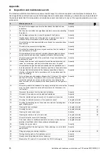
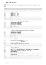
12 Inspection and maintenance
12.1
Complete Service Interval Record section
▶
After servicing, complete the relevant Service Interval
Record section of the Benchmark Checklist located on
the inside back pages of this document.
12.2
Using original seals
If you replace components, use only the enclosed original
seals; additional sealing materials are not required.
12.3
Inspection and maintenance
▶
You must carry out an annual inspection of the product.
The annual inspection can be effectively performed
without removing components by requesting data from
the DIA system, carrying out the simple visual checks in-
dicated in the table in the appendix and performing a flue
gas measurement. The maintenance intervals and their
scope are determined by the heating engineer based on
the condition of the boiler found during the inspection. All
inspection and maintenance work should be performed in
the order specified in the table in the appendix.
During any inspection and maintenance or after change
of parts of the combustion circuit, the following must be
checked:
–
The boiler has been installed in accordance with the rel-
evant installation instructions.
–
The integrity of the flue gas installation and flue seals is
in accordance with the relevant flue installation instruc-
tions enclosed.
–
Visual, the integrity of the boiler combustion circuit and
relevant seals (paying particular attention to the burner
door seal).
–
The gas inlet working pressure at maximum rate.
–
The gas flow rates.
–
Correctness of electrical, water and gas connections.
–
Correctness of the water pressure.
–
The condition of the whole system, in particular the con-
dition of radiator valves, evidence of leakage from the
heating system and dripping taps.
▶
Correct any faults before proceeding.
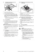
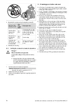
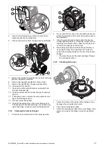
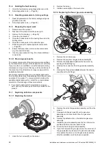
12.4
Preparing the maintenance work
1.
Switch off the product.
2.
Disconnect the product from the power grid.
3.
Remove the front casing. (
4.
Close the gas stopcock.
5.
Close the service valves in the heating flow and in the
heating return.
6.
Close the service valve in the cold water pipe.
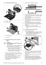
7.
Drain the product to clean hydraulic components
(
8.
Ensure that water does not drip on live components
(e.g. the electronics box).
9.
Use only new seals and o'ring. Do not use additional
compounds.
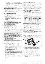
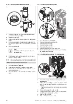
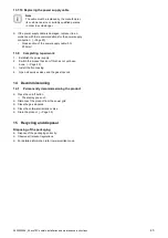
12.5
Checking the CO
₂
content
1.
Start up the product with the check programme
(P.01)
and set the value.
–
Setting value for the programme P.01: 100
Check programmes
–
Overview (
2.
Wait until the value that is read is stable.
–
Waiting period for reading a stable value: 5 min
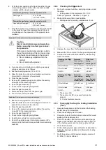
1
3.
Unscrew the cover from the flue gas analysis point
(1)
.
4.
Measure the CO
₂
content at the flue gas analysis point.
5.
Compare the measured value with the corresponding
value in the table.
Checking the CO
₂
content
Removed
front casing
Fitted front
casing
Natural gas H
Natural gas H
CO
₂
at full load
9.0
±
1.0 vol. %
9.2
±
1.0 vol. %
CO at full load
≤
250 ppm
≤
250 ppm
CO/CO
₂
≤
0.0031
≤
0.0031
Checking the CO
₂
content
Removed
front casing
Fitted front
casing
Liquefied pet-
roleum gas P
Liquefied pet-
roleum gas P
CO
₂
at full load
10.1
±
0.5 vol.
%
10.3
±
0.5 vol.
%
CO at full load
≤
250 ppm
≤
250 ppm
CO/CO
₂
≤
0.0026
≤
0.0026
◁
The value is OK.
▽
The value is not OK; you cannot start up the
product.
▶
Set the CO
₂
content. (
Summary of Contents for ecoTEC sustain 24
Page 1: ...en Installation and maintenance instructions ecoTEC sustain 24 28 34 0020253094_05 04 11 2020...
Page 61: ......
Page 62: ......
Page 63: ......


