36
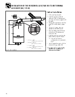
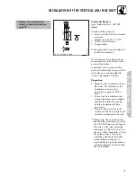
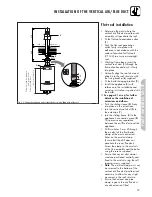
INSTALLATION OF THE VERTICAL AIR/FLUE DUCT
750
2
3
790
740
Ø125
20 – 50
°
4
5
6
40
10
8
190
7
1
8
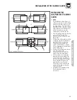
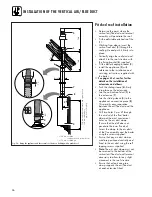
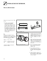
Fig. 5.2: Fitting the appliance and the vertical roof duct to a building with a pitched roof
Pitched roof installation
• Determine the point where the
vertical air/flue duct and terminal
assembly will penetrate the roof.
• Fit the adjustable pitched roof tile
(
1
).
• Working from above, insert the
vertical roof duct (
5
) through the
roofing tile and push it firmly into
place.
• Vertically align the roof duct and
attach it to the roof structure with
the fixing bracket (
6
) supplied.
• Fit the boiler hanging bracket (
2
).
• Install the appliance (
3
) with
reference to the installation and
servicing instructions supplied with
the boiler.
☞
See pages 41 et seq. for further
details on the installation of
extensions and elbows.
• Push the sliding sleeve (
4
) firmly
into place on the extensionn.
• Join the vertical roof duct (
5
) to
the extension (
7
).
• Join the sliding sleeve (
4
) to the
appliance’s connection piece (
8
).
This permits easy separation
between the air/flue duct and the
appliance.
• Drill two holes 3 mm Ø through
the air duct of the flue/boiler
clamp at the most convienient
holes on the air duct clamp.
(Ensure that the drill does not
penetrate the inner flue duct).
Screw the clamp to the air ducts
of the flue assembly and the boiler
using the screws supplied.
• Ensure that any air duct clamps
used are positioned centrally and
fixed to the air duct using the self
tapping screws supplied.
•
Note:
The air/duct clamp must not
be screwed to the bottom of the
vertical air/flue duct and terminal
accessory to allow for any slight
movement in the roof structure.
• Ensure that at least one pipe
clamp supports the air/flue duct
at each extension fitted.
*
*
= 190 mm ecoMAX
combination and system boilers
*
= 176 mm ecoMAX pro
750 mm ecoMAX combination and system boilers
530 mm ecoMAX pro
(top holes of bracket)

