5 Assembly and installation
14
Installation instructions aroTHERM 0020147164_09
5.3
Hydraulics installation
In heating installations that are equipped primarily with ther-
mostatic or electrically controlled valves, a constant and suf-
ficient flow through the heat pump must be ensured. Irre-
spective of which heating installation is selected, the min-
imum volume of circulating heating water (40% of the nom-
inal flow, see the technical data table) must be guaranteed.
5.3.1
Carrying out the hydraulics installation
Caution.
Risk of material damage caused by
residues in the pipelines.
Welding remnants, sealing residues, dirt or
other residues in the pipelines may damage
the product.
▶
Flush the heating installation thoroughly
before installing the product.
Caution.
Risk of material damage due to corrosion.
If plastic pipes that are not diffusion-tight are
used in the heating circuit, this may lead to
corrosion and deposits in the heating circuit
and in the product.
▶
Do not treat the water with corrosion pro-
tection agents if plastic pipes that are not
diffusion-tight are used.
Danger!
Risk of material damage caused by sol-
dering work.
Carrying out soldering work on lines that
have already been installed may damage the
seals.
▶
Solder the lines before installing the
product.
1.
Insulate the lines (including those running below
ground) with UV-resistant and high-temperature-res-
istant insulation between the product and the heating
installation.
2.
In order to avoid transferring vibrations to the surround-
ing buildings, use flexible connection pipes on the
product that have a length of at least 0.75 m.
3.
When the product is not installed at the highest point
in the heating circuit, install additional purging valves
in places where air can collect (elevated points in the
system).
4.
Install all of the safety-relevant hydraulic components.
Note
If you use glycol, you must collect it at the
expansion relief valve to prevent environ-
mental pollution.
Note
Improper purging of the heating circuit may
cause pump faults due to a low flow rate
(
F.532
).
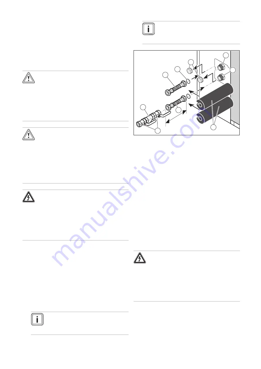
0.75 m min.
7
3
1
9
6
2
4
5
8
1
Connection hose in
the heating flow to the
building (on-site)
2
O-ring seal
3
Covering cap
4
Heating flow connection
(diameter 1 1/4") to the
building
5
Heating return connec-
tion (diameter 1 1/4") to
the heat pump
6
Connection hose in the
heating return to the
heat pump (on-site)
7
Insulation (on-site)
8
Stop valve
9
Dirt filter
5.
Remove the covering caps
(3)
from the product's hy-
draulic connections.
6.
Install a dirt filter
(9)
in the heating circuit return
between two isolation valves
(8)
so that the filter can be
cleaned regularly.
7.
Install a flexible connection pipe
(1)
and
(6)
(to be
provided on-site) with an O-ring and an isolation valve
to each of the connections for the heat pump heating
flow and return.
8.
Check the connections for tightness.
5.3.2
Connecting the swimming pool (optional)
Danger!
Risk of material damage due to a direct
connection to a swimming pool.
If the product is directly connected to a swim-
ming pool, damage may be caused by corro-
sion.
▶
Do not connect the heat pump heating
circuit directly to a swimming pool.
▶
If you want to connect a swimming pool to the heating
circuit, note the components (expansion vessels, etc.)
that are required for the installation.


