3.5 Status display
(For maintenance and service work performed by your
installer or service agent)
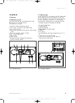
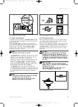
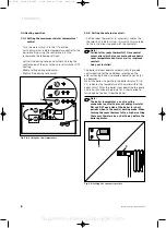
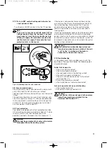
The status displays are activated by pressing the "i"
button (1). The current status code, e.g. "S.34" for the
frost protection mode, is shown on the display (2, fig.
3.10).
Pressing the "i" button again will switch you back to the
normal mode.
The "+" and "-" buttons will only be used by your
installer or service agent during service and
maintenance work.
Fig. 3.10: Status displays
Table 3.1: Status displays (A complete overview of the status
codes can be found in the installation instructions).
* Heating operation, ** Hot water operation
2
1
VRC-VC
C
o
0
I
C
o
9
Operation 3
Instructions for use aquaPLUS
9
3.6 Resetting the appliance
When a hot water tap or the central heating system
requires heat, the boiler automatically ignites and starts
to operate. If the automatic ignition is not successful
within 10 seconds, then the boiler does not go into
operation and switches to "Lock out".
This is indicated visually by the crossed out flame in the
display and the displaying of fault code "F.28" or "F.29"
(flame extinguished during operation). A new attempt to
ignite the flame can then only be performed after
pressing the "Reset" button.
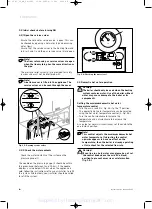
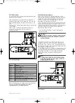
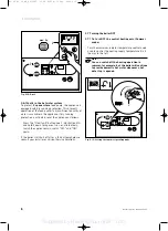
• Press the "Reset" button (2, fig.3.11) and hold for
approx. 1 second.
Warning!
If the boiler still shuts off after a third attempt,
then please consult your installer or Vaillant
Service Solutions.
The boiler also switches to "Fault" when there is not
enough water in the system. This fault is indicated by
fault codes "F.22", "F.23" or "F.24". The boiler must only
be placed back in operation after the heating system has
been properly refilled with water.
In the unlikely event of any other fault developing, which
prevents the boiler from operating, the display will also
show other fault codes. If a fault code is displayed
please contact your installer or Vaillant Service
Solutions.
Note!
If contacting Vaillant Service Solutions please
remember to quote the fault code, as this will
help to pinpoint the fault.
Fig. 3.11: Reset
C
o
0
I
C
o
VRC-VC
2
Display
Meaning
S.00*
No heating demand
S.02*
Pump running
S.03*
Ignition sequence
S.04*
Burner ignited
S.05*
Fan and water pump over run
S.07*
Water pump over run
S.08*
Anti cycling mode (after heating operation)
S.10**
Hot water demand
S.20**
Power store
cycle mode active
S.28**
Anti cycling mode (after
power store
filling)
S.34*
Frost protection mode active
83 46 41_10_GB_04/2003 11.04.2003 9:11 Uhr Seite 9
Supplied by HeatingSpares247.com

