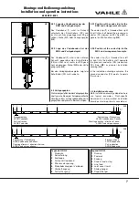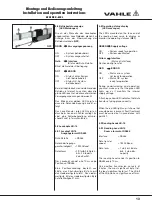
4.3.1 Lage des Codebandes bei der
KBH und Verlegebeispiel
Das Codeband (
1
) wird im Schacht
unterhalb der Schutzleiters (PE) von
rechts nach links eingezogen (auf PE ge-
sehen). Siehe (
G1
) oder Verlegungsplan
(
G3
).
4.3.2 Lage des Codebandes bei der
MKL und Verlegebeispiel
Das Codeband (
1
) wird in den unteren
Schacht gegenüber des Schutzleiters
(PE) von links nach rechts (auf PE gese-
hen) eingezogen. Siehe (
G2
) oder Verle-
gungsplan (
G4
).
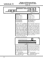
Bei den Verlegeplanbeispielen zeigt der
Schutzleiter (PE) zur Kranbahn.
4.4 Verlegungsplan
Die hier dargestellten beiden Verlegungspläne
sind typische Beispiele. Anlagenspezifische
Unterlagen bzw. auftragsgebundene Verle-
gungspläne sind primär zu berücksichtigen.
7
APOS KBH - MKL
Montage und Bedienungsanleitung
Installation and operation instructions
Einzugsrichtung
APOS-Codeband
"R"
Zählrichtung / Pfeilrichtung
APOS-Codeband und Sensor
"L"
1
2
3
{
4
5
6
7
Pull-in direction
APOS-Code strip
Counting direction / direction of arrow
APOS-Code strip und sensor
8
Legende G3/G4
1
Kranbahn
2
Schleifleitung
3
Endkappe
4
Festpunkt Codeband
5
Streckeneinspeisung
6
Stoßabdeckkappen / Verbinder
7
Gleitaufhängung
8
Festaufhängung
1
1
Legend G3/G4
1
Runway
2
Powerail
3
Endcap
4
Fixpoint code-strip
5
Line feed
6
Joint cover /Joint
7
Sliding hanger
8
Fixpointhanger
G1
G2
Einzugsrichtung
APOS-Codeband
"R"
Zählrichtung / Pfeilrichtung
APOS-Codeband und Sensor
"L"
1
2
3
{
4
5
6
7
Pull-in direction
APOS-Code strip
Counting direction / direction of arrow
APOS-Code strip und sensor
8
G4
G3
4.3.1 Position of the code strip for the
KBH and arrangement example
The code strip (
1
) is threaded from right
to left in the shaft below the ground con-
ductor (PE) (viewed on PE). See (
G1
) or
general installation drawing (
G3
).
4.3.2 Position of the code strip for the
MKL and arrangement example
The code strip (
1
) is threaded from left
to right into the bottom shaft opposite
the ground conductor (PE) (viewed on
PE). See (
G2
) or general installation
drawing (
G4
).
In the installation drawing examples, the
ground conductor (PE) points towards
the runway.
4.4 Installation drawing
Both installation drawings depicted here
are typical examples. Plant-specific
documents or order-related installation
drawings must be primarily considered.


