background image

APOS KBH - MKL

17

Montage und Bedienungsanleitung 

Installation and operation instructions

8 Fehlerbehandlung

8.1 Allgemeines

Bei einem Statusfehler am Lesekopf 
(Aufleuchten der roten LED) sind folgen-
de Punkte zu beachten:

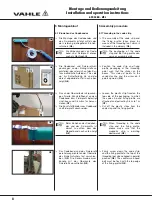
Magnetband und Lesekopfwagen 
sowie alle Kabelanschlüsse auf 
Beschädigungen überprüfen.
Defekte Baugruppen sind zu ersetzen.

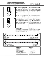
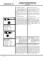
Der normale Abstand zwischen Sensor
und Magnetband beträgt bei der 
KBH etwa 3,5 mm und bei der MKL etwa
2,5 mm.

- Die Lesekopfoberseite muss spaltfrei

am oberen Anschlag des Lesekopfwa-
gens anliegen. Falls erforderlich den 
Sensorabstand neu einstellen auf
Nennmaß.

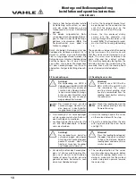
- Gesamte Fahrstrecke in Schleichfahrt

oder von Hand mit dem Lesekopfwa-
gen abfahren, um Störstelle zu lokali-
sieren.

- Falls erforderlich Entstörmaßnahmen

gemäß Punkt 8.2 durchführen.

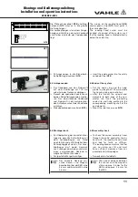
8.2 Entstörmaßnahmen

Der Schirm des Signalausgangskabels
sollte nur einseitig an die Nachfolgeelek-
tronik angeschlossen und zentral mit
Schutzerde verbunden werden. Das Sig-
nalausgangskabel ist grundsätzlich 
getrennt von Laststromleitungen zu ver-
legen und ein Sicherheitsabstand von
mindestens 0,5 m zu induktiven und ka-
pazitiven Störquellen wie Schütze, 
Relais, Motoren, Schaltnetzteile, getak-
tete Regler etc. ist einzuhalten.

Sollten trotz Einhaltung aller oben 
beschriebenen Punkte Störungen auftre-
ten, muss wie folgt vorgegangen werden:

Anbringen von RC-Gliedern über
Schützspulen von AC-Schützen 
(z.B. 0,1μF / 100 

Ω

)

- Anbringen von Freilaufdioden über DC-

Induktivitäten.

- Anbringen von RC-Gliedern über den

einzelnen Motorphasen und über der
Motorbremse (im Klemmenkasten des
Motors).

- Schutzerde und Bezugspotential 

nicht

verbinden!

- Vorschalten eines Netzfilters am exter-

nen Netzteil.

8 Fault treatment

8.1 General information

The following points must be observed in
the event of a status fault on the reading
head (red LED lights up):

Check the magnetic strip and the
reading head carrier as well as all 
cable connections for damage.
Defective assemblies must be replaced.

The normal distance between the sensor
and the magnetic strip is approx. 3,5 mm
for the KBH and approx. 2.5 mm for 
the MKL.

- The upper side of the reading head

must lie against the upper top of the
carrier as close as possible. If necessa-
ry, re-adjust the sensor distance to no-
minal value.

- Travel along the entire track by hand

with the reading head carrier at crawl
speed to localise the fault.

- If necessary, carry out fault clearing

measures acc. to point 8.2.

8.2 Fault clearing measures

The screen of the signal output cable
should only be connected to the down-
stream electronics on one side and be
centrally connected to PE. The signal
output cable must generally be laid sepa-
rately from load current cables, and a 
safety clearance of at least 0.5 m from 
inductive and capacitive sources of inter-
ference such as contactors, relays, 
motors, switching power supply, clocked
controllers etc. must be adhered to.

If faults should still occur despite 
ad herence to all points described above,
please proceed as follows:

- Attachment of RC-elements via contac-

tor coils of AC contactors (e.g. 0.1μF /
100 

Ω

)

- Mounting of free wheeling diodes via

DC inductance.

- Attachment of RC-elements via the 

individual motor phases and via the
motor brake (in the terminal box of the
motor).

- Do 

not

connect PE and reference 

potential!

- Prefix a mains filter on the external

PSU.

Summary of Contents for Apos KBH 4/200 HS

Page 1: ...gsanleitung APOS Positioniersysteme KBH und MKL Installation and operation instructions APOS positioning systems KBH and MKL Montage Inbetriebnahme Schnittstellen Wartung Installation Commissioning In...

Page 2: ...7 Contents 1 Information on the Documentation 3 1 1 Additionally applicable documents 3 1 2 Symbols used 3 2 Safety instructions 4 2 1 Personnel qualifications 4 2 2 General safety instructions 4 3 Tr...

Page 3: ...ile besch digt oder zerst rt werden k nnen und wie Sie diese Gef hrdung vermeiden k nnen H Hier erhalten Sie erg nzende Hinweise 1 Information on the Documentation 1 1 Additional documents These mount...

Page 4: ...teilen zur Vermeidung von Quetschgefahren nicht unter schritten werden 2 Safety instructions 2 1 Personnel qualifications Assembly installation and maintenance work may only be carried out by trained...

Page 5: ...berpr fen Gegebenenfalls ist die Anlage zu Reinigen und Auszurichten siehe Montageanleitung 5 APOS KBH MKL Montage und Bedienungsanleitung Installation and operation instructions a Danger of damage O...

Page 6: ...ichtung der B nder 6 There should be about 0 5 m space at the ends of the conductor line for threa ding in the code strip The end caps of the conductor line must be dismantled 4 1 Scope of delivery Co...

Page 7: ...chleifleitung 3 Endkappe 4 Festpunkt Codeband 5 Streckeneinspeisung 6 Sto abdeckkappen Verbinder 7 Gleitaufh ngung 8 Festaufh ngung 1 1 Legend G3 G4 1 Runway 2 Powerail 3 Endcap 4 Fixpoint code strip...

Page 8: ...te des Fixierprofils abschlie en G8 G5 G6 G7 G8 G9 5 Assembly procedure 5 1 Threading in the code strip The assembly of the code strip and the fixing profile takes place by means of the threading tool...

Page 9: ...das Codeband entsprechend Vorgaben im Verlegungsplan zum Schleiflei tungsgeh use festzusetzen Dies erfolgt normalerweise am Festpunkt der Schleifleitung G12 G13 G14 Insert the threading tool into the...

Page 10: ...u kontrollieren Hierbei ist darauf zu achten dass die gekennzeichnete Sensorseite nach oben zum Codeband zeigt G15 For this the fixed point bracket must be positioned on the conductor line such that t...

Page 11: ...bei der MKL etwa 2 5 mm The arrows on the reading head G16 and magnetic strip G17 must point in the same direction The reading head carrier must be inserted at one end of the system such that the read...

Page 12: ...0V 2 wei white TX 3 blau blue TX 4 schwarz black 24 VDC 5 6 Connection to the vehicle Creating the mechanical connection from the swivel head of the kelly M10 to the consumer Arrange the flexible kell...

Page 13: ...RS485 Eine Positionssendung besteht aus 3Byte das h chstwertige Byte zuerst das niederwertigste zuletzt Das nieder wertigste Bit des niederwertigsten Byte hat die Wertigkeit 1mm G22 5 8 Operating stat...

Page 14: ...nd G23 RS 485 time diagram tb2 tbyte2 8 85 ms tb1 tbyte1 0 57 ms tb0 tbyte0 0 57 ms tr trate 10 ms 5 9 2 Reading head LB 15 Source format SSI Graycode Bin rcode A shift register with the current measu...

Page 15: ...ur Demontage Neue Einspeisung von einer Seite her einschieben Verbinder montieren Die Schleifleitung ist ggfs In die Aus gangslage zur ckzuschieben Sto kappen montieren 5 10 Trial run A trail run with...

Page 16: ...r feed Connecting the power feed takes place in the reverse order of dis connecting the power feed Pull the cable with the cable gland through the new face plate and fix to same Fasten the cable shoes...

Page 17: ...en des Motors Schutzerde und Bezugspotential nicht verbinden Vorschalten eines Netzfilters am exter nen Netzteil 8 Fault treatment 8 1 General information The following points must be observed in the...

Page 18: ...18 APOS KBH MKL Montage und Bedienungsanleitung Installation and operation instructions...

Page 19: ...19 APOS KBH MKL Montage und Bedienungsanleitung Installation and operation instructions...

Page 20: ...AUL VAHLE GMBH CO KG D 59172 KAMEN GERMANY TEL 49 23 07 70 40 Internet www vahle de E Mail info vahle de FAX 49 23 07 70 44 44 DQS zertifiziert nach DIN EN ISO 9001 2008 OHSAS 18001 2007 Reg Nr 003140...

Reviews: