


Technical Manual
Instructions for installation,
operation and maintenance
641
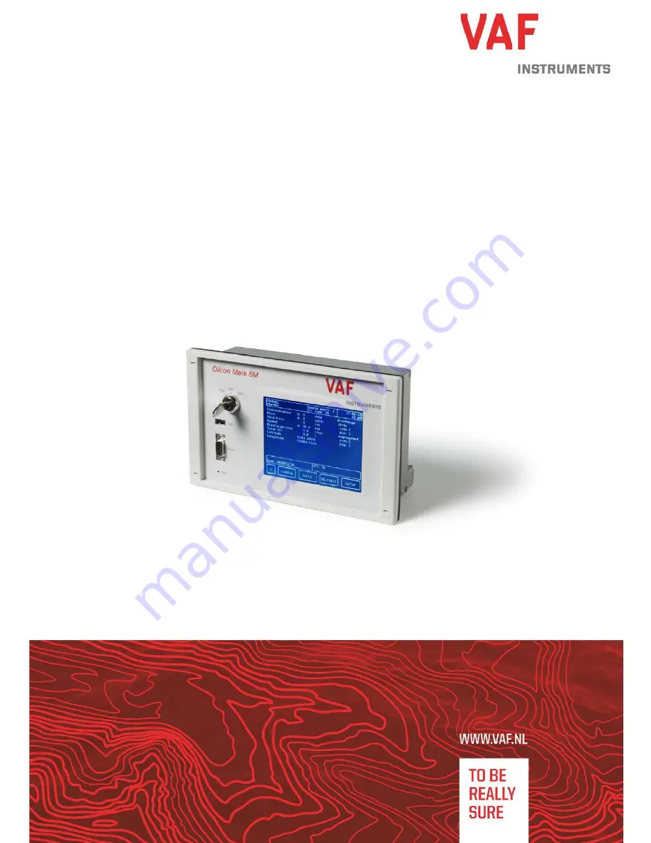
OILCON
®
MARK 6M
According regulation 31 Annex I of MARPOL 73/78,
IMO Resolution MEPC.108(49) and IMO Resolution MEPC.240(65)
Oil Discharge Monitoring and Control System
Publication nr
TIB-641-GB-1117
Supersedes TIB-641-GB-0617
Summary of Contents for OILCON MARK 6M
Page 112: ...111...
Page 113: ...112...
Page 114: ...113...
Page 115: ...114...
Page 116: ...115...
Page 117: ...116...
Page 118: ...117...
Page 119: ...118...
Page 120: ...119...
Page 121: ...120...
Page 122: ...121...
Page 123: ...122...
Page 124: ...123...
Page 125: ...124...
Page 128: ...127 Drawing 1 0806 0005 Sheet 1 2...
Page 129: ...128 Drawing 2 0806 0005 Sheet 2 2...
Page 130: ...129 Drawing 3 0806 1041...
Page 131: ...130 Drawing 4 0806 1075...
Page 132: ...131 Drawing 5 0806 1076...
Page 133: ...132 Drawing 6 0806 1077...
Page 134: ...133 Drawing 7 0806 1260 Sheet 1 2...
Page 135: ...134 Drawing 8 0806 1260 Sheet 2 2...
Page 136: ...135 Drawing 9 0806 1265...
Page 137: ...136 Drawing 10 0806 1267...
Page 138: ...137 Drawing 11 0806 1268...
Page 139: ...138 Drawing 12 0806 1279...
Page 140: ...139 Drawing 13 0806 1285...
Page 141: ...140 Drawing 14 0806 1286...
Page 142: ...141 Drawing 15 0806 1287...
Page 143: ...142 Drawing 16 0806 1288...
Page 144: ...143 Drawing 17 0806 1621...
Page 145: ...144 Drawing 18 0806 1622...
Page 146: ...145 Drawing 19 0806 2032...
Page 147: ...146 Drawing 20 0806 2048...
Page 148: ...147 Drawing 21 0806 2050...
Page 149: ...148 Drawing 22 0806 5019...
Page 150: ...149 Drawing 23 0806 5026...
Page 151: ...150 Drawing 24 0806 8016...
Page 152: ...151 Drawing 25 0806 8023...
Page 153: ...152 Drawing 26 0806 8035...
Page 154: ...153 Drawing 27 0806 8038 Sheet 1 4...
Page 155: ...154 Drawing 28 0806 8038 Sheet 2 4...
Page 156: ...155 Drawing 29 0806 8038 Sheet 3 4...
Page 157: ...156 Drawing 30 0806 8038 Sheet 4 4...
Page 158: ...157 Drawing 31 0806 8039...
Page 159: ...158 Drawing 32 0806 8040...
Page 160: ...159 Drawing 33 0806 8070...
Page 161: ...160 Drawing 34 0810 2010...
Page 162: ...161 Drawing 35 0871 1213...
Page 163: ...162 Drawing 36 0899 1092...
Page 164: ...163 Drawing 37 0899 1163...
Page 165: ...164 Drawing 38 0899 1249...
Page 166: ...165 Drawing 39 0899 1256...
Page 167: ...166 Drawing 40 0899 1258...
Page 168: ...167 Drawing 41 0899 1259...