4
5
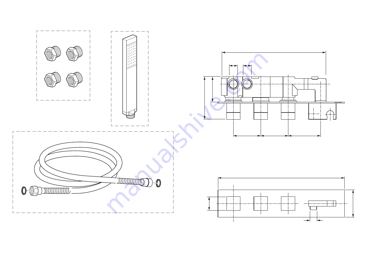
Contents of Packaging
Shower hose with 2 washers
Handset
Adaptors ¾" to ½" x 4
Dimensions
¾"
95mm
80mm
40mm
370mm
306mm
125.5mm
75-100mm
½"
Page 1: ...ep for future reference Installation Guide NOTION where inspiration flows Vado Wedmore Road Cheddar Somerset England BS27 3EB tel 01934 744466 fax 01934 744345 aftersales vado com www vado com This instruction booklet covers model TAB 128 3WO NOT CP Version 1 1 2 20 ...
Page 2: ...1999 and Scottish Byelaws 2004 For further information contact the Water Regulations department of your local water supplier see the WRAS website www wras co uk for details or the Water Regulations Advisory Scheme by email info wras co uk or telephone 01495848454 Before making any inlet pipe connections all supply pipes MUST be thoroughly flushed to remove debris Failure to do so could result in d...
Page 3: ...4 5 Contents of Packaging Shower hose with 2 washers Handset Adaptors to x 4 Dimensions 95mm 80mm 80mm 40mm 80mm 370mm 306mm 125 5mm 75 100mm ...
Page 4: ...6 7 Installation Quick guide 1 2 77mm 263mm 1 2 3 4 0 5 1 2 3 4 0 5 1 2 3 4 0 5 1 2 3 4 0 5 1 2 3 3 90mm Installation Quick guide 4 5 1 2 1 2 1 2 1 2 3 x 1 x 3 ...
Page 5: ...valve must be set into the wall between 75mm minimum 100mm maximum If you are fitting the valve to a partition wall or a wall of particularly soft substrate you will need specialist fixings Please contact VADO or retailer for WG STUDFAST C S S fixing Mortar guard During installation please leave the mortar guard secured to the valve to avoid damage to the product and protect the internals during t...
Page 6: ...red channels e g outlet 1 to the shower head outlet 2 to the bath Note outlet 3 will be connected to the handset Mortar guard Mortar guard screws Cold Hot Outlet 2 Outlet 1 Handset outlet Installation Select the position for the shower valve and offer the shower valve to the wall make sure the valve is level and mark the 6 fixing points with a suitable pencil see above for dimensions Remove the sh...
Page 7: ...er has slight adjustment Guide the handset holder onto the spigot first and then slide the cover plate over the shrouds Push the cover plate up to the wall and tighten the two grub screws on the underside of handset holder to secure it to the spigot Apply a thin bead of silicone around the outside to seal against the tiled surface Offset spline 13 Installation handset Handset outlet Place a rubber...
Page 8: ... thermometer when the handle mark is located at 12 o clock NOTE temperature readings should be taken at normal flow rate after allowing for the system to stabilise 2 If the temperature is not 38 proceed to reset the calibration as follows Do not remove the plastic stop ring Turn the spline of the valve clockwise to decrease the temperature and anti clockwise to increase the temperature until 38 is...