6
7
9
10
Installation - Quick guide
8
11
14
15a
12
13
- X mm
X mm
ZON-143-H-CP
ZON-143-CP
Page 1: ...or future reference Installation Guide ZONE Vado Wedmore Road Cheddar Somerset England BS27 3EB tel 01934 744466 fax 01934 744345 aftersales vado com www vado com Version 2 1 1 23 where inspiration flows ZON 143 CP ZON 143 H CP IND Z143 IND Z143 H ...
Page 2: ...the Water Supply Water Fittings Regulations 1999 and Scottish Byelaws 2004 For further information contact the Water Regulations department of your local water supplier see the WRAS website www wras co uk for details or the Water Regulations Advisory Scheme by email info wras co uk or telephone 01495848454 The fitting of an isolating valve to the inlet feed is advised for ease of maintenance Pleas...
Page 3: ...4 5 Dimensions 78 113mm 52mm 121mm 1 2 65mm Ø57mm 80mm 2 1 4 5 Installation Quick guide 3 x 2 113mm 78mm ...
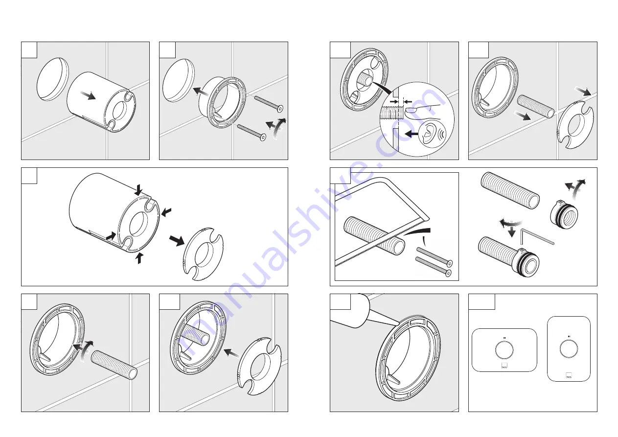
Page 4: ...6 7 6 9 10 Installation Quick guide 7 8 11 14 15a Installation Quick guide 12 13 X mm X mm ZON 143 H CP ZON 143 CP ...
Page 5: ...rk the 2 fixing points with a suitable pencil Remove the shower valve from the wall drill the holes to a suitable depth for the wall plugs and secure with suitable screws Valve Tiling guide Final wall surface On opposite side of tiling guide Maximum 113mm Fixing screws Minimum 78mm Tiling guide Outlet arrow on valve Maximum wall mark Minimum wall mark x 2 1 2 3 2 1 3 ...
Page 6: ...wall surface between the min and max marks Outlet Inlet from ZON 128 Tiling guide Outlet arrow on valve Screws Screws Remove the 2 screws using the suitable hex key provided with the ZON 128 and pullout the tiling guide After removing the blanking plug and adding the outlet adaptor to the ZON 128 connect the water supply to the right inlet of the valve Connect the outlet arrow on valve to the desi...
Page 7: ...e cartridge 13 Installation Measure the distance X mm the rod protrudes from the level of the spacer plate and then unscrew the rod and remove the spacer plate Note Ensure the cartridge is pushed in the off position X mm X mm Rod Spacer plate Extension rod Cap Hex key Screw the cap onto the rod until it s flush and tighten the grub screw on the cap using the smaller hex key provided with the ZON 1...
Page 8: ...With the correct cover orientation use the screws to locate the holes in the valve body Fit the rubber washer place the button onto the cap of the extension rod and screw the rod onto the spindle of the cartridge Make sure the cover is level and tighten Cover Button x 2 Cover Rubber washer Cap 1 3 2 ZON 143 CP ZON 143 H CP the screws using the suitable hex key provided with the ZON 128 to secure t...