background image

Advice on sowing

72

Ver.07/06/01 07/06/01

4.5

Tramlining

The tramline options possible and the settings on the Control Box are described in ”3.16.3 Pro-
gramming the Type III Control Box” on page 54 
and ”3.16.8 Tramline options” on page 62.

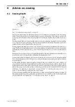
During sowing, the most important thing to remember about tramlining is to shut off Autostep
before doing anything other than normal sowing or turning in headlands between bouts.

So, remember to switch Autostep off before raising the drill to pass an obstruction.

When stopping to re-fill the hopper or for a rest period, raise the drill out of the last bout and wait
10 seconds. Then turn off AutostepAutostep does not have to be turned off, however, if no other
lifting is to be done during the rest period. Move the switch back to Autostep before the drill is
raised for the first time once work is resumed.

4.6

Bout markers

The Control Box setting for the markers are described in ”3.16.4 Settings and functions” on page
58. 
See also 4.7 Obstructions” on page 72 and ”4.8 Turning with Low lift” on page 72.

Once a reliable setting for the bout markers has been found, it is a good idea to mark this position
using e.g. a centre punch. Check occasionally that the marker tines are securely tightened.

The final tillage operation before sowing should preferably not be done in exactly the same direc-
tion as that intended for sowing, but at a slight angle to it.

4.7

Obstructions

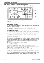
Switch off Autostepsee “Figure 3.43” point 16before the drill is raised to sow around a post,
well or other obstacle.

NOTE!

When the drill is raised to clear an obstruction during a bout, the drive wheel will also be

raised, which stops the seed feed. This can occur even with very slight raising of the drill.

During sowing, the bout markers can be retracted to avoid an obstruction by moving the Lift stop
switch, see “Figure 3.43” point 17, to the down position and moving the hydraulic lever to lift po-
sition. The markers will now fold in while the drill remains in work. Extend the markers again. In
this case, neither Autostep nor the multiple selector for the markers needs to be moved.

4.8

Turning with Low lift

When the drill is lifted out of work at the headland, the drive wheel is raised and the bout marker
is retracted. If Low lift is activated, the drill will be raised to Low lift height.

When the drill is raised at the headland the bout markers and tramlining sequence is automatically
advanced one position. If the drill will not lift, Lift stop is probably switched on, with the switch
in the down position. If the markers and tramlining do not advance automatically, Autostep is pro-
bably switched off.

When turning in Low lift, the following harrow remains in work during the entire turn.

NOTE!

Before reversing the machine, Low lift must be switched off and the drill raised to the full

lift position.

Summary of Contents for RAPID RD F Series

Page 1: ...Ver 1 3 07 06 01 900107 en Instructions Seed drill RAPID series RD 300 450 F No 10 026 11 999...

Page 2: ...2 Ver 1 3 07 06 01...

Page 3: ...t L g Low Niedrig Bas 12x100 kg ha Uts de Cereals Getreide C r ales 26x10 kg ha Oljev xter Oil seed lpflanze Plante ol agineuse Se 3 15 See 3 15 Siehe 3 15 Voir 3 15 Tag alltid ett utmatningsprov S ta...

Page 4: ...nce bout marker mfg no 10 309 24 2 16 Fitting the pre emergence bout marker mfg no 10 310 26 3 Instructions and settings 3 1 Tractor 27 3 2 Hitching the seed drill 28 3 3 Adjusting hose length and con...

Page 5: ...ission Mfg No 10 158 78 5 5 Drive wheel transmission 78 5 6 Locking device RD 400 450 F 78 5 7 Push rod push rod ram 79 5 8 Cleaning 79 5 9 Storing the drill 80 5 10 Lubrication points 80 5 11 Changin...

Page 6: ...6 Ver 1 3 07 06 01...

Page 7: ...orough quality assurance inspection and function test ing before delivery The user purchaser shall retain sole liability for ensuring that the equipment is functioning correctly when in use V derstad...

Page 8: ...400 450 F Never walk under a suspended section Always check that the automatic catches have engaged in connection with transport and parking To ensure reliable operation of the automatic lock grease...

Page 9: ...when the machine is not on the field G Do not climb onto the wheels when the seed drill is parked as they can rotate H Do not stand on the seed drill while it is in use Do not stand on the seed hoppe...

Page 10: ...cturing Number Always state this number in connection with orders of spare parts ser vice or warranty claims 1 5 2 CE plate Figure 1 5 C Working width D Transport width E Serial CE number F Weight unl...

Page 11: ...from the front in the places indicated by the labels When lifting using lifting straps secure them to the centre sections RD 300 F or in the folded up wings RD 400 450 F in the placed indicated by th...

Page 12: ...n delivery 2 3 Fitting the pre implements Fit the pre implements as explained in the spare parts manual or in certain cases according to the attached instructions 2 4 Fitting the drawbar Figure 2 4 Fi...

Page 13: ...freeplay of a few millimetres Check that the drive wheel can be raised and lowered by hand without the lifting ram jamming between the links Fit the drive shaft B using the R clips C Check that the c...

Page 14: ...n fan Position the tractor and drill at the maximum turning angle without connecting the PTO shaft If the power outlet is not central position the tractor to the side giving the shortest shaft length...

Page 15: ...the fan Connect the fan transmitter and area meter to the cable harness The cables are numbered and the corresponding number is on the cable harness Attach the outer tubing on the area meter cable to...

Page 16: ...Assembly instructions 16 Ver 07 06 01 07 06 01...

Page 17: ...since poor contact will cause malfunction Make sure that the connecting cable to the drill is not trapped under the rear window of the tractor as this may cause damage Use a hatch or a hole Clamp the...

Page 18: ...marker shaft towards the mounting lug C and drive in the pin A under the washer Fit the circlip K again Fold out the bout marker and release the marker ram Switch on the control box and turn the left...

Page 19: ...y that the bout marker arm passes across the roller but is not under tension when folded in Also verify that the bout marker arm is not affected by the post harrow linkage when it is raised or lowered...

Page 20: ...e attached to the platform B Adjust the stop screws C so that the brackets A rest very lightly on the R clips D when there is no load on the platform 2 12 2 Installing the front platform mfg no 10 310...

Page 21: ...n the scraper blade and the tyre should be at least 5 mm To check this Let the drill rest on the discs with the wheels a few centimetres over the ground Rotate the wheels and check that the scraper bl...

Page 22: ...ide section NOTE The double shafts are of left hand and right hand pattern Fit the following harrow sections to the shafts Fit the centre and left hand following harrow sec tion on the right hand side...

Page 23: ...RD 300 450 F Ver 1 3 07 06 01 23...

Page 24: ...off the engine and switch off the control box Do not stand on the wheels when fitting the pre emergence bout markers since they may rotate 2 15 1 Fitting the pre emergence bout markers for centre mar...

Page 25: ...line spa cing matches the selected tramlining See 3 17 1 Adjusting track width on page 64 2 15 3 Fitting the hydraulic system Figure 2 21 Remove the three plugs E from the outlets marked 8 and 9 at th...

Page 26: ...light connectors K in the frame joints and assemble the frame parts Adjust the space D to the correct tramline spacing Verify that this tramline spacing matches the selected tramlining see 3 17 1 Adj...

Page 27: ...es or similar Aim for as low an inflation pressure as possible Any front end weights on the tractor should be removed Two two way hydraulic connectors are required If the seed drill is equipped with a...

Page 28: ...es with plastic rings are used to raising and lowering the seed drill and to operate the markers The two thin 1 4 hoses marked with plastic rings are used to fold down the side wings and adjust the fr...

Page 29: ...tem Also read section 3 15 Adjusting the air flow on page 42 prior to starting the fan 3 3 Adjusting hose length and connecting intermediate cable Figure 3 7 The machine is fitted with an adjustable h...

Page 30: ...aw the wings together with the folding ram Note Do not operate the folding ram in the wrong direction in this position At the same time unlock the wing sections with the line C Unfold the wing section...

Page 31: ...to prevent the seed coulters becoming clogged F Lower the tool bar to its working position 3 4 2 Changing to transport position A Switch off the low lift function at the control box Raise the seed dr...

Page 32: ...meter First pack the soil lightly then scrape away thin layers of soil until the seeds are exposed The seeds in all rows should ap pear simultaneously If they do not the drill is not fully level Figu...

Page 33: ...Adjustment of the centre section drilling depth is made using the stop bolt A The drilling depth of the side sections is adjusted with the cranks B The scale indications do not constitute absolute va...

Page 34: ...the stop bolt A needs to be adjusted first fold up the machine again see 3 4 Changing bet ween transport position and working position RD 400 450 F on page 30 3 8 Adjusting the changeover valve 3 8 1...

Page 35: ...epth settings or incorrect adjustment of the wing sections see 3 6 Adjusting sowing depth on page 33 and 3 7 Adjusting the wing sections on page 34 3 9 2 RD 300 450 F Figure 3 22 The working depth of...

Page 36: ...he seed being crushed Electric adjustment of the sown amount Option If the machine is equipped with electric adjustment of the sown amount option the seed house setting is operated using the power swi...

Page 37: ...The scale is practically linear making a procentual increase or decrease possible Example We want a sowing rate of 220 kg ha wheat and set a scale reading of 50 The cali bration test gives a value of...

Page 38: ...uspended load Make sure there is nobody on the drill when feeding the seed Use of an extension handle on the knife blade is recommended Make sure there is nobody on the hopper Mfg no 10 309 Figure 3 3...

Page 39: ...ed load Make sure there is nobody on the drill when feeding the seed Make sure there is nobody on the hopper Figure 3 32 The stepping boards and platform of the drill are not designed for manual loadi...

Page 40: ...st Figure 3 34 To check the actual output a running test can be performed This is recommended especially when the seed drill is new or is used on a different surface to the previous one When sowing in...

Page 41: ...RD 300 450 F Ver 1 3 07 06 01 41...

Page 42: ...1 1 3 15 2 Hydraulic fan Mfg No 10 158 Figure 3 36 The air quantity is controlled by the fan rev speed which is set using the rev speed regulator A on the fan support On tractors with a constant pres...

Page 43: ...3 16 3 Programming the Type III Control Box on page 54 Warm up the hydraulic system before running the fan on full 10 minutes for most tractors Under NO circumstances should the fan should be run on...

Page 44: ...hydraulic system but no flow valve the fan speed is instead controlled with a check valve installed on the pressure line between the tractor and the sowing machine The check valve can be ordered as a...

Page 45: ...ol box See 3 16 3 Programming the Type III Control Box on page 54 NOTE During operation the oil can become very hot more than 80 C Prior to starting Check that all hoses and screws are secure Check th...

Page 46: ...mper The damper has four positions Refer to the table below for recommended settings Sliding damper position 1 fully opend Small Grass seed The fourth or between third and fourth position depending on...

Page 47: ...RD 300 450 F Ver 1 3 07 06 01 47...

Page 48: ...t Ensure that the coupling pro perly connects with the shaft 2 Install the top rod in the top rod mount of the tractor Please note the use of two mounting points 3 Install the hydraulic pump to the to...

Page 49: ...um speed of 3800 rpm and a maximum speed of 4800 rpm The alarm limits can be adjusted in the control box For more in formation see 3 16 3 Programming the Type III Control Box on page 54 NOTE During op...

Page 50: ...per The damper has four positions Refer to the table below for recommended settings Sliding damper position 1 fully opened Small Grass seed The fourth or between third and fourth position depending on...

Page 51: ...t markers can be switched off by tur ning switch A to the up position Low lift Function Sowing must always be carried out with Low Lift on Switch B in the middle position to allow optimal hydraulic fu...

Page 52: ...firms selected settings 11 SET button allows changes to tramline spacing 12 Spare switch not in use 13 button increases tramline spacing 14 button decreases tramline spacing Press the SET button and c...

Page 53: ...r more OK Red flashing light voltage under 12 V TOO LOW 26 Electric adjustment of the seed volume Option Figure 3 53 27 Main switch Tests all functions automatically when turned on 28 Automatic fuses...

Page 54: ...the symbols on the Cal1 strip on the Box 1 Switch the Box on while pressing button 6 Cal1 appears in the RH display The selected setting has been stored only when ENTER stops flashing in the LH displa...

Page 55: ...gives a more accurate measure of the area covered from the start since it takes soil conditions into account wheel slip stones etc The speed shown is also more accurate after calibration of the autom...

Page 56: ...e control box is later switched on it is in the drive mode 8 Resetting If the Box begins to behave strangely or the text in the displays becomes illegible then a fault has occurred in the processor Su...

Page 57: ...will access the Cal2 calibration programme E Press button 14 on the control box F Run the setting device against the scale value 0 on the seed box using the minus button on the remote control NOTE Imm...

Page 58: ...are activated when the hydraulic takeoff for lifting and lowering is moved Obstructions If there is an obstruction in front of a marker Lift stop must be activated to allow the marker to be moved wit...

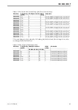
Page 59: ...an revs X X Left fore feed sensor X X Right rear feed sensor X X Fuse fault Err4 FUSE Tramlining X X Table 3 6 Version 16 Mfg No 10 164 Version 19 Mfg No 10 165 0 No tramlining 0 No tramlining 1 10 St...

Page 60: ...amount to use this function the drive wheel must be turning Flick the switch C briefly downwards to reduce the sown amount the scale value then decreases to the next ten digit percentage value The E2...

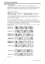
Page 61: ...the fault before resetting the fuse 3 16 7 Tramlining flaps Tramlining is carried out by the spring loaded tramlining flaps A which are integrated into the out lets of the seed distributor heads in th...

Page 62: ...Adjusting track width on page 64 Tramlining of various spacings is set using the and buttons on the Control Box see 3 16 2 Functions of the Control Box on page 52 Bring up the starting values for the...

Page 63: ...F 16 m 4 2 First bout half overlapped by the second bout RD 400 F 20 m 5 3 RD 400 F 24 m 6 3 First bout half overlapped by the second bout RD 450 F 9 m 2 1 First bout half overlapped by the second bou...

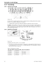
Page 64: ...left and the fore right one step inward Y For bigger changes in track width it may be necessary to move the ho ses inside the hopper instead 3 17 2 Adjusting row shutoff Figure 3 63 Tramlining can be...

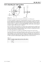
Page 65: ...ound clearan ce The following harrow should be adjusted so that it remains in working position when tur ning with the drill in Low lift at headlands This eradicates the tracks left by the drill during...

Page 66: ...th the drill during service or maintenance without first ensuring that it is safely supported on stands and that all lifting rams are locked There is 1 lifting ram to control sowing depth of the drill...

Page 67: ...ss the coulters closer to the discs as the nuts are tightened The nuts should not be tightened so much that the coulters cannot be rocked by hand It is important that the coulters do not press too har...

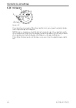
Page 68: ...adjusted NOTE Under no circumstances should the distance between the edge of the scraper blade and the tyre be less than 5 mm This is to prevent damage to the scraper and the tyre The scraper should a...

Page 69: ...lds with varying soil type sowing depth should be checked and adjusted continually to en sure that the correct sowing depth is maintained throughout the field Sowing depth must be adjusted with the ai...

Page 70: ...function and check if these coulters are now deli vering seed Get into the routine of quickly looking over the drive shafts gears and chains to see that everyth ing looks normal and is still in place...

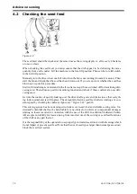
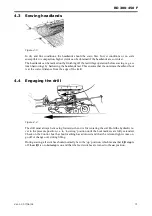
Page 71: ...ost headland bout is at the correct distance from the edge of the field 4 4 Engaging the drill Figure 4 4 The drill must always be moving forwards when it is first entering the soil Hold the hydraulic...

Page 72: ...exactly the same direc tion as that intended for sowing but at a slight angle to it 4 7 Obstructions Switch off Autostep see Figure 3 43 point 16 before the drill is raised to sow around a post well o...

Page 73: ...tivator making sure that the final pass is not in the same direction as that intended for sowing The first cultivation should be done as soon after harvest as possible with subsequent cultivation s an...

Page 74: ...uld be 4 cm when drilling cereals on clay soils The pressure and angle of the following harrow should be adjusted so that wheel tracks are er adicated This is a very reliable method of establishment 4...

Page 75: ...ot development gets some heat into the soil and allows any subsequent pan formation to be dealt with Shallow placement of the seed is important on silty soils to ensure rapid emergence before a sur fa...

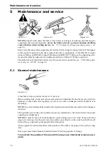
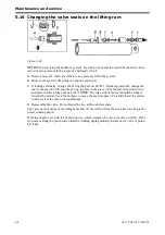
Page 76: ...ge 66 5 1 General maintenance Figure 5 4 A machine is only as good as the service it receives Before starting work check that all nuts and screws are tightened During the season check the tightness of...

Page 77: ...the transparent transmission cover when necessary Check that the blades of the cellwheel do not jam but that they bear against the bottom of the groo ve during setting from zero and upwards Check the...

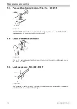
Page 78: ...and axle of the lower fan pulley and the drive axle 5 5 Drive wheel transmission Figure 5 9 Remove the chain casing and check the tension in the chain and the condition of the chain Grease the chain e...

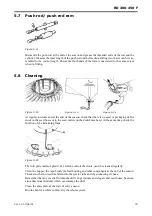
Page 79: ...k in the seed hoses or in the seed outlets on the distributor head At the same time check the function of the tramlining flaps Figure 5 15 The turn plate made of plastic A which controls the doors mus...

Page 80: ...again 5 10 Lubrication points Be safety conscious and do not crawl under the drill to lubricate Lubricate from above or support the drill securely on trestles See 1 Safety regualtions on page 8 Lubric...

Page 81: ...nsist of a ball bearing which is pressed onto the disc hub and secured with a circlip Cir clip pliers and a puller should be use to dismantle the bearing A special puller can be ordered from V derstad...

Page 82: ...g a few washers and a nut not a lock nut Grease the threads of the washers and nut well and draw the bolt in using the nut Be sure to use enough washers so that the nut does not go beyond the thread o...

Page 83: ...rams completely from the drill before changing the seals A Loosen and unscrew the piston rod guide A using the special tool B B Withdraw the piston rod and change the seals In the event of external l...

Page 84: ...First put the O ring in place in the groove Put the seal in hot water first and press it into a kidney shape to fit it NOTE The edge side of the seal should be turned towards the piston Use a blunt o...

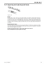
Page 85: ...maged area may be cut off It the hose is too stiff with the joint and cannot be bent sufficiently when the drill is folded it may be necessary to replace the entire hose or to move part of the hose an...

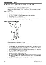
Page 86: ...inutes This will also clean the new oil that was filled up 5 18 2 Oil and filter replacement Figure 5 26 Replacement interval 200 hours or every 2nd year NOTE The breathing filter should be replaced a...

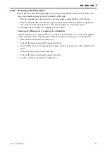
Page 87: ...from the system Refit the hose and tighten the coupling but not too hard Start up after filling up oil or replacing the oil and filter After having filled up or replaced the oil air will be mixed with...

Page 88: ...e the lid and tighten by hand In order to bleed the system and to clean the filled up oil as well operate the fan while keeping the tractor at idle for a couple of minutes see below 5 19 2 Oil and oil...

Page 89: ...up with oil Starting after filling up oil or replacing the filter and oil When filling up or replacing the oil air will mix with the oil in the tank This air must be removed prior to operation of the...

Page 90: ...k that the relevant indicator lights are working properly Check that the ends of the intermediate cable are correctly connected to the Control Box and drill respectively Check all 37 pole connectors a...

Page 91: ...oids It should always be possible to retract both bout mar kersv regardless of the setting or indication on the Control Box Check as in 6 1 2 Hydraulic faults on page 90 Bout marker s unfold slowly Ch...

Page 92: ...ar right of the valve is receiving current See Hydraulic solenoid valves under 6 3 Notes on troubleshooting on page 97 If there is no current to the sole noid valve See 6 1 1 Electrical faults on page...

Page 93: ...nd at least 35 l min Check for short circuits in the sensor cable Check the inductive sensor see 6 3 Notes on trou bleshooting on page 97 The fan indicator never lights Check the upper and lower fan r...

Page 94: ...Box on page 54 For too low area speed readings increase this value For too high area speed readings decrease this value One or more tramlining flaps fails to open close Both tramlining motor should b...

Page 95: ...16 Changing the valve se als on the lifting ram on page 84 Does the depth stop reach the upper plate of the pis ton If so the spring has been compressed or dama ged The discs do not spin freely Are th...

Page 96: ...tor and remove the quick connector Start the fan Collec the drained oil in a container Measure the pressure Measure the amount of oil exi ting during one full minute A considerable pressure drop would...

Page 97: ...ent is getting to the bout marker solenoid valves B when the relevant indicator lights up to the Lift stop valve C when its switch is down or when Low lift is activated at Low lift height and to the p...

Page 98: ...thin 1 1 5 mm Easily tested since a diode on the back edge of the sensor lights up every time it registers an object Capacitive sensor Figure 6 5 Responds to objects containing moisture seed a hand et...

Page 99: ...The input signals are poles 10 16 20 21 22 23 and 24 For poles 20 22 23 and 24 the input signal is earthing repeated with varying frequency Earths The earths are poles 5 6 7 and 8 These are parallel...

Page 100: ...75 515 Kg l 10 20 30 40 50 60 70 80 90 100 110 120 130 140 H g High Hoch Haut L g Low Niedrig Bas 12x100 kg ha Uts de Cereals Getreide C r ales 26x10 kg ha Oljev xter Oil seed lpflanze Plante ol agine...

Page 101: ...RD 300 450 F Ver 1 3 07 06 01 101 7 2 Calibration Results Table 7 2 Crop kg dm High low gear Scale reading 10 20 30 40 50 60 70 80 90 100 110 120 130 140...

Page 102: ...ic ram RH bout marker 4 Hydraulic ram LH bout marker 5 Hydraulic ram pre emergence bout marker 6 Hydraulic ram tool bar 7 Valve block Lift stop bout markers pre emergence markers 8 Tractor A Solenoid...

Page 103: ...e emergence bout marker 6 Hydraulic ram tool bar 7 Hydraulic ram folding 8 Valve block Lift stop bout markers pre emergence markers 9 Valve block folding 10 Strangler non return valve 1 0 mm 11 Change...

Page 104: ...fan standard mftg no 10 259 Figure 7 3 A Flow valve B Hydraulic motor C Choke valve D Manometer E Radiator F Tractor 7 3 4 Fenix fan standard mftg no 10 260 10 323 Figure 7 4 A Cut off valve B Hydraul...

Page 105: ...1 105 7 3 5 Fenix fl kt standard 3 hose design mftg no 10 324 10 622 A Hydraulic motor B Radiator C Tractor 7 3 6 Fenix fl kt standard 3 hose design mftg no 10 623 Figure 7 5 A Hydraulic motor B Valve...

Page 106: ...Ver 07 06 01 07 06 01 7 3 7 Fenix fan PTO mftg no 10 949 Figure 7 6 A Hydraulic pump B Hydraulic motor C Choke valve D Radiator E Air filter F Oil filter G Waste valve H Hydraulic tank I Tractor B C...

Page 107: ...3 07 06 01 107 7 3 8 Fenix fan PTO mftg no 10 950 Figure 7 7 A Hydraulic pump B Hydraulic motor C Choke valve D Radiator E Air filter F Oil filter G Contamination indicator H Hydraulic tank I Tractor...

Page 108: ...Appendices 108 Ver 07 06 01 07 06 01 7 4 Electrical diagram Figure 7 8 307335...

Page 109: ...e left bout marker Normally closed C Magnetic valve lift stop Normally open D Magnetic valve pre emergence about marker Normally closed E Inductive detector fan speed Normally open F Inductive detecto...

Page 110: ...ne monitoring Pink white 20 B9 Speedometer area meter Green Input signal Ground 21 B10 Lift acknowledgment Yellow Input signal Ground 22 B11 Rotation guard White Input signal Ground 23 B12 Rotation gu...

Page 111: ...iguration Connector pole Cabling pole Cable colour Function 1 24 Grey Signal 2 36 Brown 12V 3 5 Blue Ground Table 7 5 Area meter configuration Connector pole Cabling pole Cable colour Function 1 20 Gr...

Page 112: ...3 5 Ground 4 19 Signal 5 36 12V 6 5 Ground Table 7 8 Configuration Connector pole Cable Colour Function 1 Motor Green Tramlining off 2 Motor Black Tramlining on 3 Motor Blue Ground 4 Detector Black Si...

Page 113: ...3 0 Transport height m 2 55 2 55 2 55 Hopper capacity litres 2000 2000 2000 Max load in hopper kg 2000 2000 2000 Max trailed weight on tractor kg 1850 2000 2300 Disc weight each approx kg 145 127 126...

Page 114: ...590 21 V DERSTAD S 590 21 V DERSTAD SWEDEN Telefon 0142 820 00 Telephone 46 142 820 00 Telefax 0142 820 10 Telefax 46 142 820 10 Hemsida http www vaderstad com Homepage http www vaderstad com...

Reviews: