Instructions and settings
62
Ver.07/06/01 07/06/01
3.16.8 Tramline options
The RD 300-450 F models are supplied with equipment for centre marking installed.
The RD 450 F models are fitted to order with either centre marking or side marking. In centre mar-
king the lines will be symmetrical in relation to the centre line of the drill. In side marking a line
is marked on the left-hand side of the seed drill in the course of two consecutive bouts.
The drill is supplied having two or three row shutoff. If one row shutoff is required, it can be ac-
hieved by changing the flap springs for the outlets which are not required to tramline, see ”3.17.2
Adjusting row shutoff” on page 64.
For control or alteration of the track width, see ”3.17.1 Adjusting track width” on page 64.
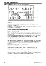
Tramlining of various spacings is set using the + and - buttons on the Control Box, see ”3.16.2
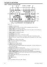
Functions of the Control Box” on page 52. Bring up the starting values for the first bout using the
manual step button 15. Tramlining is in operation when lights 5 are on. For successful tramlining,
it is essential to work out the tramline layout before starting work.
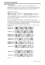
Example: RD 400 F to produce 24 m tramlines. Set the multiple selector to 6 (24/4=6). Advance
to a start value of 3.
Figure 3.61
Table 3.7 Tramlining options
RD 300 F 6, 9, 12, 15, 18, 21, 24 metre
RD 400 F centre marking 8, 12, 16, 20, 24 metre
RD 400 F side marking 16, 24 and 32 metre
RD 450 F centre marking 9, 18, 27 metre
RD 450 F side marking 18, 27 and 36 metre
RD 300 F/6 m
RD 400 F/12 m
RD 300 F/12 m
RD 400 F/16 m
RD 500 F/18 m
RD 600 F/24 m
RD 800 F/27 m
RD 450 F/9 m
RD 450 F/ 18 m
RD 300 F/15 m
RD 400 F/20 m
RD 300 F/24 m
RD 450 F/18 m
RD 450 F/27 m
Summary of Contents for RAPID RD F Series
Page 1: ...Ver 1 3 07 06 01 900107 en Instructions Seed drill RAPID series RD 300 450 F No 10 026 11 999...
Page 2: ...2 Ver 1 3 07 06 01...
Page 6: ...6 Ver 1 3 07 06 01...
Page 16: ...Assembly instructions 16 Ver 07 06 01 07 06 01...
Page 23: ...RD 300 450 F Ver 1 3 07 06 01 23...
Page 41: ...RD 300 450 F Ver 1 3 07 06 01 41...
Page 47: ...RD 300 450 F Ver 1 3 07 06 01 47...
Page 108: ...Appendices 108 Ver 07 06 01 07 06 01 7 4 Electrical diagram Figure 7 8 307335...

