


WallVIEW PRO HE100
WallVIEW PRO HE100 Installation and User Guide 341-790 Rev. B
Page 3 of 12
INSTALLATION
All WallVIEW products are specifically designed for installation on a vertical wall surface with Cat. 5 cable
connectivity for Power, Video and Control signaling (three cables are required). Installation is simplified in
that no custom 8-Pin mini-din cables or expensive S-Video plenum cables are needed and no power outlets
are required near the camera bracket. All cabling is routed to the head-end using Cat. 5 cables.
Before Installing
•
Locate the camera mounting location paying close attention to camera viewing angles, lighting conditions,
possible line of site obstructions, and checking for in-wall obstructions where the camera is to be
mounted. Pick a mounting location to optimize the performance of the camera.
•
Pre-wire all cabling as required (see wiring diagram examples).
•
The Wall Mount for the WallVIEW PRO HE100 can be mounted directly to a 3-gang wall box or can be
mounted to the drywall using four dry wall anchors.
MOUNTING INSTRUCTIONS
Step 1:
After determining the optimum location of the camera system, route the required 3 (three) Cat. 5 cables from
the camera to the Quick-Connect Pro interface located at the head-end. The three Cat. 5 cables should
feed-through the oval slot located on the rear flange of the wall mount (Figure 4). If the bracket is to be
mounted on a 3-gang wall box, use the screws supplied with the wall box cover plate to attach the Thin
Profile Wall Mount. If mounting to the drywall with wall anchors, use four (4) quality wall anchors. The
mounting holes are slotted and are 90° opposing to provide easy leveling. Level the mount and tighten down
the mounting screws. A fourth Cat. 5 cable is required if simultaneous SD video is desired (see p. 5).
Step 3:
Connect the 25-pin end of the break out cable to the EZIM. Next, mount
the EZIM to the back of the wall mount on the left side, using the two
tapped screw holes (see Figure 4). Connect the 15-pin video cable,
power connector. NOTE: The Cat. 5 cable for RS-422 control is
connected directly to the “Controller” port on the back of the HE 100.
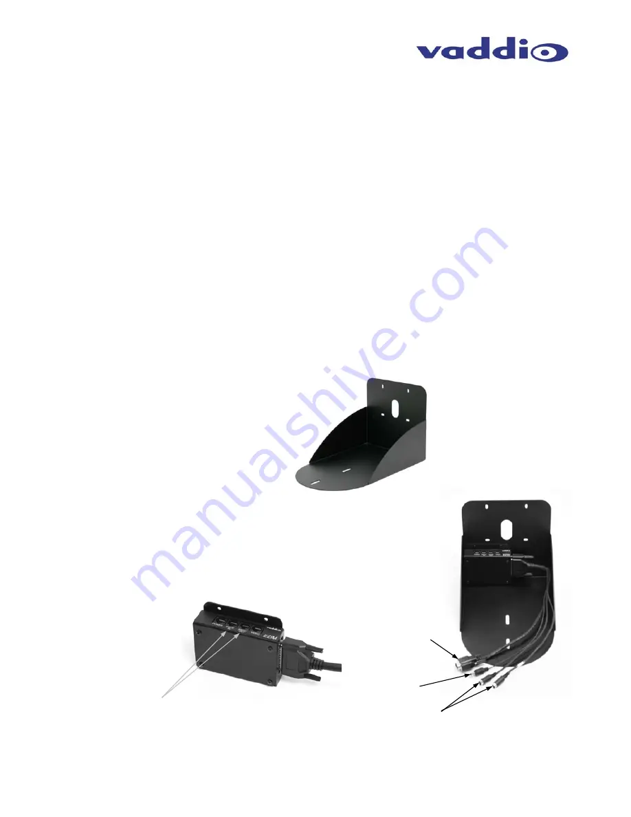
Figure 3:
Thin Profile Wall Mount with oval cable
feed-through hole. The wall mount may be
mounted directly to a 3-gang wall box or to
the dry wall with the appropriate wall
anchors.
Figure 4:
25-pin break out
cable connected to
EZIM (left); EZIM
and break out cable
installed in Wall
Mount (right).
RS-232 IN & OUT are not used with the HE
100. Connect the RS-422 Cat. 5 cable to the
camera’s Controller port.
Mini-DIN 8
Connectors are not
used with the HE 100
Power XLR-4-Pin F
Connector
HD Video - DE-15F
(D-Sub 15-pin HD - F)