VADDIO WallVIEW HD-USB SR System Installation And User Manual Download Page 13

 WallVIEW HD-USB SR Camera System 


WallVIEW HD-USB SR

 Camera System,

 Document Number 342-0465 Rev. D    

Page 13 of 40 


Step 4:

  Leave the IR out OFF (up) as default. 


Step 5:

  Use 9600bps for control speed as default. 


If the camera is mounted inverted, then set the Image Flip to ON, otherwise leave it off. 

  The test bars


are really, really, totally non-standard (horizontal - just to mess with the old-timers) and will 

override the video output.  These test bars are 75% IRE.  Use the test bars for…testing.
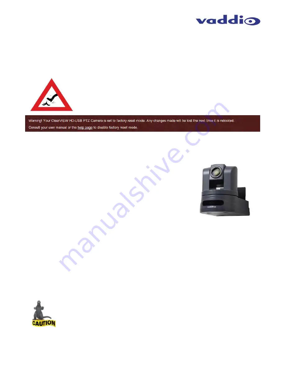


A Cautionary Note:  

In the event that the rotary switch was moved from “

0

” and left on 

“C” - RESET - RESTORES TO FACTORY DEFAULTS, 

and is power cycled, all data 

will be lost.  Sometimes a RESET is required, but those occasions are generally few 
and far between.  On the web pages, a warning dialog box was added to inform the 
administrator the state of the switch.  If the factory reset is not desired, please move 
the switch back to “

0

” and do not power cycle the camera.  The warning looks almost 

exactly like the warning below…


S

TEP BY 

S

TEP 

I

NSTRUCTIONS TO INSTALL THE 

W

ALL

VIEW


HD-USB


SR


C

AMERA 

S

YSTEM


Step 1: Locating the Camera 

Locate the camera mounting position while paying close attention to camera 
viewing angles, lighting conditions, possible line of site obstructions, and 
checking for in-wall obstructions where the camera is to be mounted.  Pick a 
mounting location to optimize the performance of the camera.    
 
Like all Vaddio WallVIEW systems, the WallVIEW HD-USB SR is easy to install 
and operate.  The product was specifically designed with CAT-5 cable 
connectivity for the extension of power and an Active USB 2.0 Extension cable 
that is powered by the computer’s USB port.   
 

Step 2: 

After determining the optimum location of the camera system, run a CAT-5 cable and the Active USB 2.0 
Extension Cable from the computer location to the camera location.  Make sure to mark and test the CAT-5 cable 
and use real RJ-45 crimper and connectors using the 568B straight-through wiring standard.  Please do not use 
the “feed-thru” type RJ-45 connectors for professional installations. 
 

Step 3: 

Using the CONCEAL wall mount directions, install the CONCEAL mount.  If mounting to the drywall with wall 
anchors, use four (4) quality wall anchors.  Make sure to level the mount and tighten the mounting screws.  

 
Step 4: 

Connect the CAT-5 cable to the EZ POWER VIDEO RJ-45 port on the back panel of the HD-USB camera.  
Connect 1’ (305mm) USB 2.0 Cable Type-B Male into the USB Type-B Female on the back panel of the HD-USB 
camera.  Connect the Active USB Extension Cable’s Type-A Female to the 1’ (305mm) USB cable’s Type-A Male 
Connector.  Field dress the cabling and tuck it back into the CONCEAL mount and place on the back cover to 
hide all the cabling. 


NOTE:  Check all Cat-5 cables for continuity in advance of the connection.  Do not plug the Cat-5 
cable into any other RJ-45 port but the EZ POWER VIDEO port.  There is 24 VDC Volts on Pins 1 & 2.  
Plugging into any other port may cause damage to the camera system and void the warranty.


Step 5:  At the Head-End 

Plug the Active USB Extension Cable Type-A Male directly into the computer.  Plug the other end of the CAT-5 
cable into the RJ-45 port of the Power Extension Module.   
 

WallVIEW HD-USB 

with CONCEAL Mount 

Summary of Contents for WallVIEW HD-USB SR System

Page 1: ...er 342 0465 Rev D Camera Software Revision 2 1 0 WallVIEW HD USB SR System Featuring the ClearVIEW HD USB PTZ Camera CONCEAL Mount Active USB Extension Cable and Power Extension Module Part Numbers 99...

Page 2: ...WallVIEW HD USB SR Camera System WallVIEW HD USB SR Camera System Document Number 342 0465 Rev D Page 2 of 40...

Page 3: ...ram Example using A CDN for release 2 0 when IP is enabled 11 First Time Set up with the ClearVIEW HD USB PTZ Camera 11 Getting Started 12 Table Switch Setting Label on Bottom of the HD USB Camera 12...

Page 4: ...built around a 1 3 Type Sony Exmor progressive scan high speed low noise CMOS image sensor with a total of 1 3 Megapixels for precise and vibrant HD color video images The HD USB achieves improved pi...

Page 5: ...IR Remote Commander One 1 EZCamera Control Adapter RJ 45 to DB 9 One 1 Vaddio PowerRite 12 VDC 3 0 Amp Power Supply One 1 AC Cord Set for North America One 1 10 3 05m USB 2 0 Type A Male to USB B Male...

Page 6: ...ons on available resolutions and concurrent resolutions when using USB 2 0 and analog component outputs 3 Camera Settings Dip Switch Settings Settings for IR remote frequency baud rate SD output forma...

Page 7: ...ion C is used for a reset to factory defaults To reset the camera and erase all the stored internal data place this switch on C and power cycle the camera Move the switch to 0 again for normal operati...

Page 8: ...mic elements and three 3 Acoustic Echo Cancellers per mic Cat 5e Cable Cat 5e Cable USB 2 0 Cable PC HD Video Bose FS 16F Ceiling Speakers Optimized for Voice WallVIEW HD USB with CONCEAL Mount Host...

Page 9: ...xample the camera is powered by the provided 12 VDC 3 0 Amp power supply CAT 5 Cable 24 VDC Power Pin 1 Pin 2 24 VDC 2 75A Power Supply Power Extension Module The 24VDC connection from the Power Exten...

Page 10: ...e Jabber Google Microsoft Lync and others This configuration features driverless USB 2 0 Video and Acoustic Echo Cancelled AEC Audio HD USB Conferencing Camera PC with Host Application USB 2 0 using o...

Page 11: ...ce Diagram Connection Diagram Example using A CDN for release 2 0 when IP is enabled For a Large Number of Viewers Use a CDN Content Distribution Network such as WOWZA Amazon or iCloud and more FIRST...

Page 12: ...olution closest to what the UC client wants to send and display For concurrent USB 2 0 and Analog Component YPbPr switch settings 0 through 6 are the resolutions that can be both digital USB 2 0 or H...

Page 13: ...y designed with CAT 5 cable connectivity for the extension of power and an Active USB 2 0 Extension cable that is powered by the computer s USB port Step 2 After determining the optimum location of th...

Page 14: ...refox the latest and current release auto updating Compatibility Soft Codecs HD USB Camera is compatible with the following soft codecs or applications in no particular order Release 2 0 x 1 Skype Win...

Page 15: ...ns Format Resolution Frame Rate Aspect Ratio MJPEG 1280 x 720 15 30 16 9 960 x 544 15 30 16 9 704 x 576 15 30 4 3 640 x 480 15 30 4 3 640 x 360 15 30 16 9 424 x 240 15 30 4 3 352 x 240 15 30 4 3 320 x...

Page 16: ...n automatically turns off To see the IP address for longer than the 15 seconds at boot up then 2 Pick up the Vaddio IR Remote Commander and find the Data Screen button 3 Press and hold the Data Screen...

Page 17: ...isplayed It is best to record the addresses that are in the computer so they can be re assigned when the operation is finished Enter 169 254 1 2 which is the default address 169 254 1 1 plus 1 and Sub...

Page 18: ...or tighter shots it is recommended that the slower speed is used 4 Store Preset Button Clicking the Store button opens up a Store Preset pop up dialog box To set presets set up the camera shot click o...

Page 19: ...f 40 Admin Pages Clicking on the Admin link button will open the Log in window Enter the default password password on this line and click on Log in After Login the Admin link buttons are exposed and i...

Page 20: ...here the colors are more vivid 3 The IP Streaming Video Settings allow the selection of the target performance for the IP Streaming The HD USB camera is set up for a variable bit rate which is much si...

Page 21: ...name room name room phone and help phone on a per camera basis The labels appear on every page at the top middle of the page Simply enter the room information and click Save By clicking on the Networ...

Page 22: ...on Save to keep the Static IP information By clicking on the Security link button the UPDATE user PASSWORD and UPDATE admin PASSWORD control sections are displayed The default user password is passwo...

Page 23: ...yed These diagnostics may help the Vaddio technical support team diagnose a problem with the HD USB camera The System link button is where the Firmware Updates will be loaded There will be several fir...

Page 24: ...ile and click on Begin Firmware Update When in doubt call Vaddio Tech Support for assistance After clicking on Begin Firmware Update a confirmation pop up and warning will be displayed Please contact...

Page 25: ...do not interrupt the firmware load Service Help information can be found under the Help tab Support phone numbers and e mail manuals FAQ s and System information is listed on this page Have this page...

Page 26: ...ly describe the steps to plug in the HD USB camera and get an image Skype Example 1 First with a quality USB 2 0 cable plug the USB B port of the camera to the USB A port of the computer A pop up wind...

Page 27: ...RTSP Streaming HLS Streaming apple s variant of HTTP streaming Release 2 H 264 Resolutions Release 2 0 x CIF 640x480 VGA 480p 720p 30 1080p 30 1080p Ethernet only User Control Vaddio IR Remote Command...

Page 28: ...by Vaddio can affect emission compliance and could void the user s authority to operate this equipment ICES 003 Compliance ICES 003 Issue 4 2004 This digital apparatus does not exceed the Class A limi...

Page 29: ...from Vaddio s technical support Provide the technician with a return phone number e mail address shipping address product serial numbers and original purchase order number Describe the reason for repa...

Page 30: ...rect 8x 01 04 08 00 FF 8x 01 04 08 02 FF 8x 01 04 08 03 FF 8x 01 04 08 2p FF 8x 01 04 08 3p FF 8x 01 04 38 02 FF 8x 01 04 38 03 FF 8x 01 04 38 10 FF 8x 01 04 48 0p 0q 0r 0s FF pqrs Focus position CAM_...

Page 31: ...e room is not exactly easy The friendly name is preferred over a generic term for firms with more than one camera The camera s scaler for lower resolutions has been improved The HD USB camera is optim...

Page 32: ...his release A detailed list of all interoperability findings can be found in the EasyUSB Tools Interoperability FAQ document Table HD USB PTZ Camera and UC Client Software Interoperability Testing Sof...

Page 33: ...nt Version WBS 28 7 and above is compatible with Vaddio USB devices Improved Interoperability with Various UC software Clients Additional USB video resolution support was added to the UVC endpoint to...

Page 34: ...are Set Example COMMAND camera pan right RESPONSE OK Get Example COMMAND stream mode get RESPONSE streaming mode usb Syntax Error Example COMMAND camera pan right SPONRESE ERROR Additional programming...

Page 35: ...he camera down stop Stop the camera movement speed Optional integer from 1 20 that represents the speed Default 10 EXAMPLES camera tilt up Tilts the camera up at the default speed camera tilt down 20...

Page 36: ...er a complete line is read Listed below are examples of history expansion Substitute the last command line N Substitute the Nth command line absolute as per history command N Substitute the command li...

Page 37: ...ork settings get ping count count size size destination ip DESCRIPTION Method used to get the current network settings or check network OPTIONS settings Get the current network settings ping Send ICMP...

Page 38: ...current streaming resolution 1080p Set video resolution to 1080p 720p Set video resolution to 720p 4cif Set video resolution to 4cif 480p Set video resolution to 480p cif Set video resolution to cif E...

Page 39: ...p switches in down position off Returns the factory reset status system factory reset on factory reset software on factory reset hardware off Enables factory reset upon reboot System Reboot NAME syste...

Page 40: ...ww vaddio com 2012 Vaddio All Rights Reserved Reproduction in whole or in part without written permission is prohibited Specifications and pricing are subject to change without notice Vaddio ClearVIEW...

Reviews: