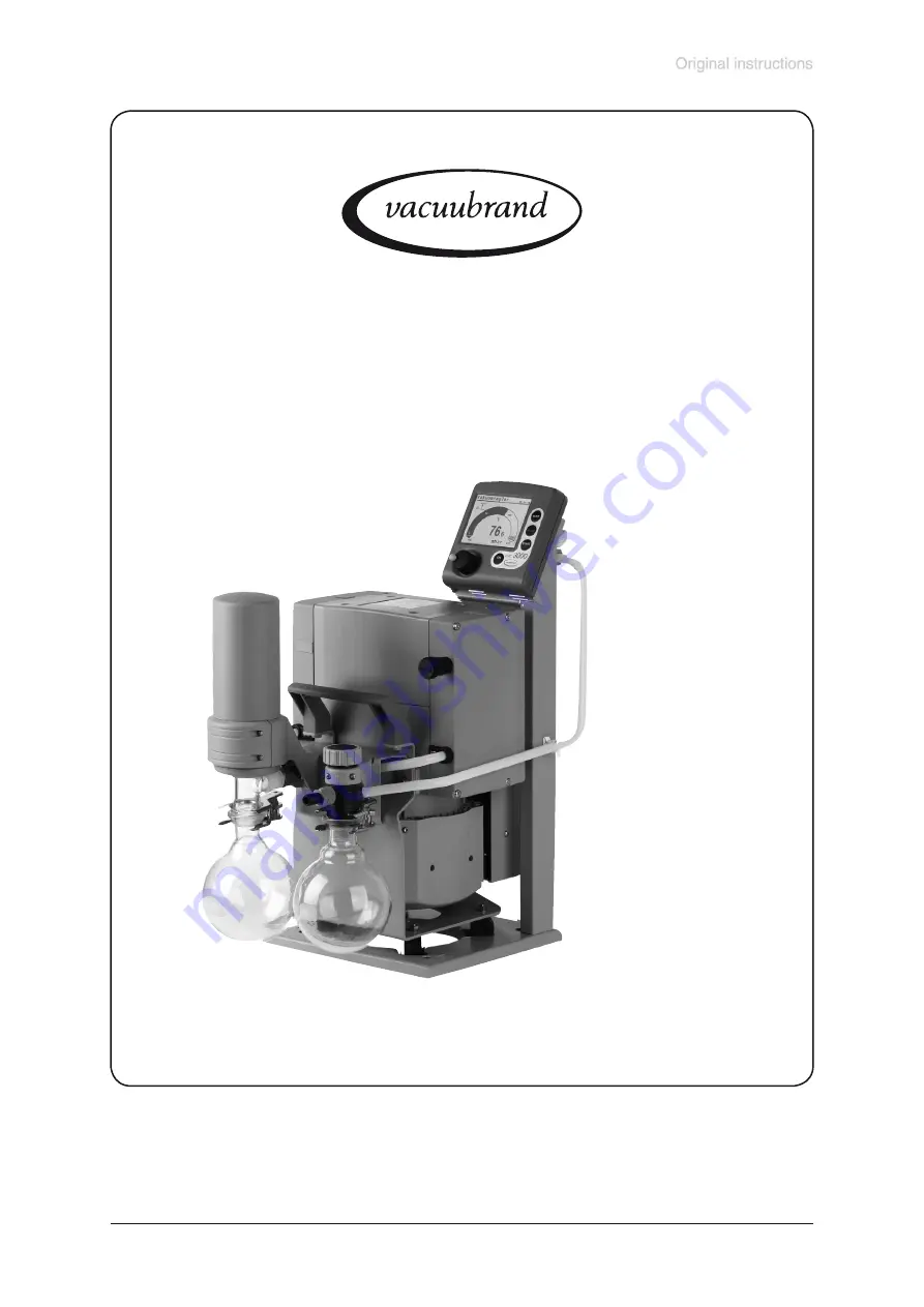
background image

Documents are only to be used and distributed completely and unchanged. It is strictly the users’ responsibility to check carefully 

the validity of this document with respect to his product. Manual-no.: 999164 / 19/05/2009

page 1 of 75

Speed controlled chemistry diaphragm pumps

and chemistry pumping  units

Instructions for use

Technology for Vacuum Systems

 ME 4C NT VARIO

 MZ 2C NT VARIO

 MD 4C NT VARIO

MV 10C VARIO-B

 MD 12C VARIO-B

PC 3002 VARIO

 PC 3003 VARIO

 PC 3004 VARIO

PC 3010 VARIO

 PC 3012 VARIO

Summary of Contents for MD 12C VARIO-B

Page 1: ...is document with respect to his product Manual no 999164 19 05 2009 page 1 of 75 Speed controlled chemistry diaphragm pumps and chemistry pumping units Instructions for use Technology for Vacuum Syste...

Page 2: ...maxim is the zero fault principle Every diaphragm pump leaving our company is tested intensively including an endurance run of 18 hours Therefore also faults which occur rarely are identified and can...

Page 3: ...lidity of this document with respect to his product Manual no 999164 19 05 2009 page 3 of 75 Portugu ycc Polski Nederl CVC 3000 V2 0 Deutsch English Fran ais Italiano Espa ol T rk e Reset Language sel...

Page 4: ...mples for use 38 Vacuum for filtration and suction 38 Vacuum for gel dryer drying chambers and vacuum concentrators 38 Vacuum for distillation and evaporation e g rotary evaporator 39 Fore vacuum for...

Page 5: ...signed for ambient temperatures during operation between 10 C and 40 C Check the maximum temperatures if installing the pump in a cabinet or a housing and make sure ventilation is adequate Install an...

Page 6: ...hanically stable and that all fittings are secure Ensure a stable po sition of the pump without any mechanical contact except of the pump feet Comply with all applicable safety regulations Position th...

Page 7: ...umped me dia Ensure that the materials of the wetted parts are compatible with the pumped substances see section Technical data Safety during operation Adopt suitable measures to prevent the release o...

Page 8: ...ate precautions to protect people from the effects of dangerous sub stances chemicals thermal decomposition products of fluoroelastomers wear appropriate safety clothing and safety glasses Check the o...

Page 9: ...nated before maintenance and take adequate precautions to protect people from the effects of dangerous substances if contamination has occurred Before starting maintenance vent the pump isolate the pu...

Page 10: ...issible ambient temperature storage operation C 10 to 60 10 to 40 Permissible relative atmospheric moisture during operation no condensation 30 to 85 Power electric W 575 No load speed min 1 30 2400 M...

Page 11: ...sture during operation no conden sation 30 to 85 Power electric W 575 No load speed min 1 30 2400 Maximum permissible range of supply voltage 10 Attention Observe specifications of rating plate 100 12...

Page 12: ...85 Power electric W 575 No load speed min 1 30 2400 Maximum permissible range of supply voltage 10 Attention Observe specifications of rating plate 100 120 V 50 60 Hz 200 230 V 50 60 Hz Maximum nomina...

Page 13: ...surement uncertainty absolute after careful adjustment and at constant temperature 1 mbar 0 75 Torr Temperature coefficient 0 07 mbar K 0 05 Torr K Ambient temperature range operation 10 C to 40 C Amb...

Page 14: ...ed Inlet pumps VARIO B Stainless steel Outlet pumps VARIO B ETFE Silencer hose to silencer PBT PVF PVC Fittings pumps VARIO B PC 301x VARIO ETFE ECTFE Tubing PTFE Pumping unit Inlet pumping unit PC 30...

Page 15: ...Diaphragm pump NT VARIO 2 Controller CVC 3000 3 Mains connection 4 ON OFF switch 5 Pump rating plate 6 Fan 7 Inlet 8 Outlet 9 Gas ballast valve 10 Fuse holder Position Component 11 Recessed grip hand...

Page 16: ...unchanged It is strictly the users responsibility to check carefully the validity of this document with respect to his product Manual no 999164 19 05 2009 page 16 of 75 MD 4C NT VARIO 4 1 5 8 2 6 9 7...

Page 17: ...ly the users responsibility to check carefully the validity of this document with respect to his product Manual no 999164 19 05 2009 page 17 of 75 underside terminal box 1 5 2 14 9 7 15 16 17 4 10 3 1...

Page 18: ...ibility to check carefully the validity of this document with respect to his product Manual no 999164 19 05 2009 page 18 of 75 outlet side MD 12C VARIO B outlet side MV 10C VARIO B MV 10C VARIO B MD 1...

Page 19: ...cument with respect to his product Manual no 999164 19 05 2009 page 19 of 75 Connection of the VACUU BUS line to NT VARIO VARIO B pump bushes for connection of VACUU BUS components e g coolant valve s...

Page 20: ...ottling losses by using connecting pipes with large diameter and by keeping them as short as possible In case of perturbing exhaust noise connect an exhaust hose or use a silencer see Accessories Inst...

Page 21: ...ring the pump Lifetimes of diaphragms and valves are enhanced Improves vacuum in case of condensation Round bottom flasks PC 300x VARIO Both round bottom flasks are coated with a protective layer to p...

Page 22: ...outlet of the pump have to be drained and disposed of appropriately Due to the high compression ratio of the pumps the pressure at the outlet port might get higher than the maximally permitted pressur...

Page 23: ...reased Use inert gas at the air inlet to avoid the formation of explo sive mixtures Close gas ballast valve by turning it 180 gas ballast open In case of low boiling solvents when the formation of con...

Page 24: ...discharge of dangerous gases and vapours to the surrounding atmosphere Ensure that the coolant outlet pipeline is always free and that it cannot get blocked Check the overpressure safety relief device...

Page 25: ...d to condensate Allow the pump to continue to run at atmospheric pressure for a few minutes continuous pumping Has the pump been exposed to media which may damage the pump materials or forms deposits...

Page 26: ...equest When switching on the controller CVC 3000 for the very first time a menu to select the language of the controller menu is displayed Select the desired language e g English by turning the select...

Page 27: ...lashing Coolant valve switched on Venting valve switched on PC symbol controller is in remote operation Time meter is running in function VACUULAN remaining time in minutes is dis played 00 00 00 Vacu...

Page 28: ...to the connected components Depending on the connected components e g valves some menu items might not be active Changing the function Switch controller on Press START STOP to terminate control in ca...

Page 29: ...ntrol Auto mode Program VACUULAN Configuration Back Configuration Adjustment 1013 mbar RS 232 Sensors Display Autostart Off Defaults Cancel Back 1013 2 mbar Auto mode 1013 2 mbar VACUULAN Auto mode Se...

Page 30: ...ess time is without effect if the process is stopped due to a preset Mini mum before Duration is reached Delay Delay determines the time the coolant valve is running on after the process has been stop...

Page 31: ...ler switches to function Vac control the current vacuum is used as set value Pressing key MODE again switches to function Auto mode The controller adapts the boiling pres sure starting from the curren...

Page 32: ...vacuum The Speed is adjustable in a range of 1 100 or can be set to HI Maximum An upper pressure limit can be preselected The pump switches off if the pressure limit is exceeded e g at the end of suct...

Page 33: ...e to this switching When pressing key STOP the controller is in function Vac control again Adjustment of the set vacuum during vacuum control Dynamic interactive adaptation Press the selection knob an...

Page 34: ...ounts of solvents The Minimum is adjustable in a range of 2 1060 mbar or can be set to Auto or to Off Delay Delay specifies the time the coolant valve continues to run after process stop The Delay is...

Page 35: ...n can be edited Time Process runtime for each program step to reach a preset vacuum level or if setting Step runtime after having achieved the vacuum level The summed up total process runtime is shown...

Page 36: ...ng and auto matic distillation with timing Program step 1 should be always a definite initial state here atmospheric pressure ATM To reach this state definitely set a tickmark at Vent and Step press s...

Page 37: ...within 100 hours the controller signals an error The Set vacuum is adjustable in the range of 1 1060 mbar Switch on If the pressure exceeds the pressure for switching on pumping down starts again The...

Page 38: ...if the con troller is not part of a pumping unit Assemble electrical connections Connect coolant if necessary Vacuum for filtration and suction Select function Pump down If necessary set value for Spe...

Page 39: ...ching After pressing key START STOP the controller is in Vac control again alternatively Fully automatic determination and adaptation of the boiling point recommended Select function Auto mode Start p...

Page 40: ...or RTS CTS and remote on On or Off Sensors Selection of the pressure transducer to be controlled maximum 4 external sensors Display Selection of the device parameters Brightness between 0 100 Contras...

Page 41: ...measurement connection of the CVC 3000 to a pressure 0 1 mbar e g by applying a good two stage rotary vane pump In function Configuration select program Adjustment at the controller The reading is aut...

Page 42: ...ration of the controller set the controller to Remote off in menu configuration Therefore switch off the controller Switch on the controller and press selection knob within 2s A maximum of ten command...

Page 43: ...ntrol without automatic 3 vacuum control with automatic maloperation mode IN_ERR XXXX 1 last command to interface incorrect 1 maloperation mode pressure transducer 1 overpressure 1 fault pump electron...

Page 44: ...TOP X 1 termination of process control 2 termination of process control and storage of the current pressure as new set point Remote operation REMOTE X 0 set controller to local operation 1 set control...

Page 45: ...n off 1 remote operation on 1 9 sensor quantity 1 9 sensor number 0 remote module not connected 1 remote module connected 0 level sensor not connected 1 level sensor connected 0 fault indicator not co...

Page 46: ...enting valve open 0 coolant valve closed 1 coolant valve open 0 in line valve closed 1 in line valve open 0 pump off 1 pump on Description Response XXXXXX XXXXXXXXX Operation Status process control Fa...

Page 47: ...in program step y 0 9 pressure in program step y 0 9 software version Response XXXX mbar or XXXX Torr or XXXX hPa XXX XXXX mbar or XXXX Torr or XXXX hPa XX XX h m XXXX mbar or XXXX Torr or XXXX hPa X...

Page 48: ...001 to 0795 Torr unit according to preselection 0001 to 1060 mbar hPa or 0001 to 0795 Torr speed in 100 HI unit according to preselection 0001 to 1060 mbar hPa or 0001 to 0795 Torr hh mm hours minutes...

Page 49: ...if connected Parameter X X X X X X X Operation mode Command START STOP REMOTE ECHO CVC OUT_VENT STORE OUT_SENSOR 2 RxD 5 Mass 3 TxD 7 RTS 4 DTR 8 CTS 9 5V Bluetooth If remote operation is selected or...

Page 50: ...0 8 mm for assembly directly at the valve head 636274 at inlet of ME 4C NT VARIO MD 4C NT at outlet of ME 4C NT VARIO MZ 2C NT VARIO Adapter to PTFE tubing DN 10 8 mm for assembly directly at the valv...

Page 51: ...ge we offer only a small selection of VACUU LAN options Please refer for further informa tion For additional accessories such as vacuum valves small flange components vacuum gauges or vacuum controlle...

Page 52: ...dity in the measurement chamber Let the pressure transducer dry e g by pumping Read just if necessary Determine and eliminate the cause for humidity Pressure transducer contami nated See Cleaning the...

Page 53: ...troller does not respond when pressing keys except ON OFF PC symbol is displayed Controller in remote mode Control CVC 3000 via in terface or switch off remote mode Controller does not respond when op...

Page 54: ...p too hot Allow pump to cool down Determine and eliminate the cause of overheating Pressure below Minimum in Auto mode Adapt switch off pressure Minimum if necessary Pump too noisy Loud exhaust noise...

Page 55: ...ure that the pump cannot be operated accidentally Never operate the pump if covers or other parts of the pump are disassembled Never operate a de fective or damaged pump Before starting maintenance is...

Page 56: ...onjointly with the assembled valve heads and fittings To maintain the diaphragms the valve heads and the fittings don t have to be disassembled The head covers can be removed conjointly with the assem...

Page 57: ...d It is strictly the users responsibility to check carefully the validity of this document with respect to his product Manual no 999164 19 05 2009 page 57 of 75 Fittings and tubing of the different pu...

Page 58: ...his product Manual no 999164 19 05 2009 page 58 of 75 PC 3003 VARIO PC 3004 VARIO PC 3002 3003 3004 VARIO at inlet side Open the hose clip at the inlet of the pumping unit hose connection to controlle...

Page 59: ...our cylinders Check diaphragm for damage and replace if necessary Lift diaphragm carefully sidewise Never use a spiky or sharp edged tool to lift the dia phragm Use the diaphragm key to grip the diaph...

Page 60: ...a phragm clamping disc to pump chamber Make sure that the square head screw of the diaphragm clamping disc is correctly seated in the guide hole of the diaphragm support disc Lift diaphragm at the sid...

Page 61: ...valve seat Valve head with gas ballast or hose nozzle connection Insert square nut in the groove of the head cover or posi tion square nut in the groove and screw on connection fastener afterwards Fi...

Page 62: ...ith a hex key size 5 then tighten Recommended torque 12 Nm Slot the blinds into the head cover Slip connecting tube onto hose connection of valve head Slide on the tube and the hose clip until touchin...

Page 63: ...ip remove flask and drain condensate Observe applica ble regulations when disposing of condensate which may be contaminated by pumped chemicals Disassembling pump from base plate Lay the pump on its s...

Page 64: ...mp heads Do not remove the elbow fittings from the pump heads Through reassembly a leak may result View of the disassembled pump head parts 8 7 6 5 4 3 2 1 14 12 13 11 17 10 9 15 16 2 1 Housing cover...

Page 65: ...th housing cover insert together with the head cover the valves and the O rings Never remove parts by using a spiky or sharp edged tool e g screw driver we recommend to use a rubber mallet or compress...

Page 66: ...of washers The pump will not attain ultimate vacuum Too many washers Clamping disc will hit head cover noise or even blockade of the pump Position new diaphragm between diaphragm clamping disc with s...

Page 67: ...ng beside valve Pay attention that the diaphragm stays positioned centrally so that it will become clamped uniformly between housing and head cover Screw in four socket head screws fixing the housing...

Page 68: ...s three times Ensure that the PTFE bond ends flush with the fittings hose connector thread Note position of valve and remove Check valve for damage and replace if necessary Make sure that the valve is...

Page 69: ...side the rating plate of the pump has to be on top support pump suitably Note that to install the console the exhaust waste vapour condenser and the condensate flask must be on top Push the console o...

Page 70: ...of this document with respect to his product Manual no 999164 19 05 2009 page 70 of 75 Replacing the device fuse fuse holder Unscrew the fuse holder using a screw driver Replace the defective fuse by...

Page 71: ...nditions with every product returned for repair We submit quotations only on request and always at the customer s expense If an order is given the costs incurred are offset from the costs for repair o...

Page 72: ...he returned product that neither toxic corrosive biologically active explosive radio active nor contamination dangerous in any way has occurred the product is free of dangerous substances the oil or r...

Page 73: ...turer Par la pr sente nous d clarons que le dispositif d sign ci dessus est conforme aux prescriptions de base des directives EU applicables et indiqu s en ci que concerne conception dessin et mod le...

Page 74: ...nous d clarons que le dispositif d sign ci dessus est conforme aux prescriptions de base des directives EU applicables et indiqu s en ci que concerne conception dessin et mod le vendu par nous m mes...

Page 75: ...s obtained under test conditions for specific applications depend on a number of factors beyond our control It is therefore strictly the users responsibility to very carefully check the validity of ap...

Reviews: