vacon • 18
STO AND SS1 SAFETY FUNCTIONS
Local contacts: https://www.danfoss.com/en/contact-us/contacts-list/
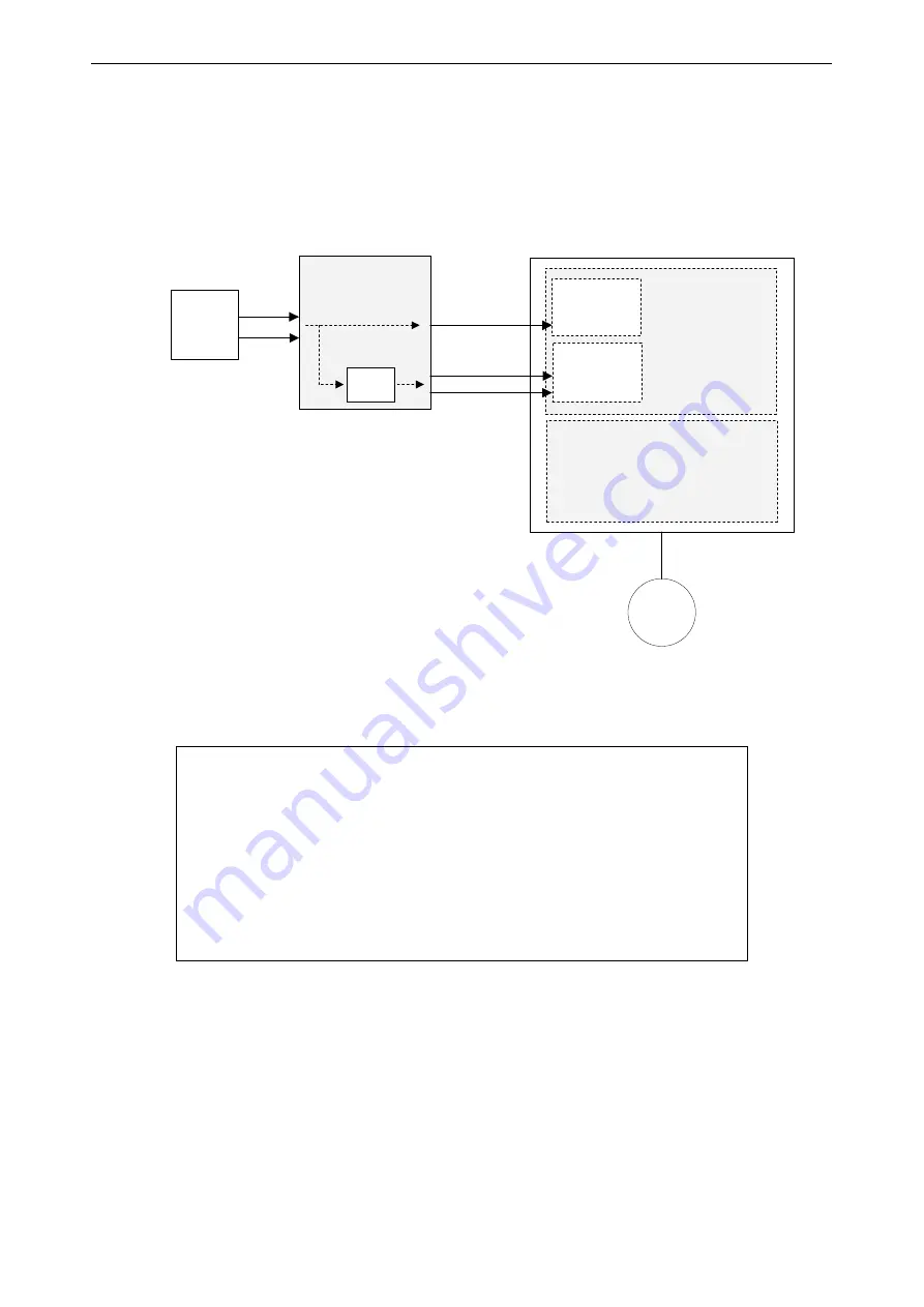
Figure 7 shows the connection principle of Safe Stop 1 safety function.
-
The time delayed safety relay outputs are connected to the STO inputs.
-
A separate digital output from the safety relay is connected to a general digital input of the
VACON
®
NX drive. The general digital input must be programmed to detect the drive stop
command and initiates without time delay the drive stop function (must be set to "stop by
ramp") and causes motor deceleration.
Figure 7. The connection principle of Safe Stop 1 (SS1)
See Chapter 3.5.5 concerning the parametrizing of Safe Stop 1 and Chapter 3.4.4 "Example 4" for
the wiring of Safe Stop 1.
CAUTION!
The system designer/user is responsible of understanding and
setting the time delay of the safety relay, due to the fact it is process/
machine dependent.
→
The time delay must be set to a greater value than the deceleration
time of the drive. The motor deceleration time is process/machine
dependent.
→
The stop function of the drive needs to be correctly set for the pro-
cess/machine.
M
STO ch1
STO ch2
Digital input
OPT-AF
OPTAx
NXP control
Power Unit
Safety Relay
with timer
Switch
Time
Delay
OPTBx
Ramp stop
STO
11056.emf
Summary of Contents for OPTAF
Page 1: ...vacon nx ac drives optaf sto and atex option board user manual ...
Page 2: ......
Page 8: ...vacon 6 GENERAL Local contacts https www danfoss com en contact us contacts list ...
Page 9: ...GENERAL vacon 7 Local contacts https www danfoss com en contact us contacts list ...
Page 10: ...vacon 8 GENERAL Local contacts https www danfoss com en contact us contacts list ...
Page 11: ...GENERAL vacon 9 Local contacts https www danfoss com en contact us contacts list ...
Page 12: ...vacon 10 GENERAL Local contacts https www danfoss com en contact us contacts list ...


