background image

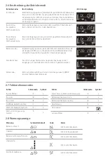
Warning

Icon (Flashing

Code 

Alarm

EPO Enabled

Sounds every 2 seconds

Over temperature

Sounds every 2 seconds

Charger Failure

Sounds every 2 seconds

Battery fault

Sounds every 2 seconds
(UPS will turn off )

Battery replacement

Sounds every 2 seconds

EEPROM error

Sounds every 2 seconds

Note

:  “Site Wiring Fault” function can be enabled/disabled via software. Please check soft-

ware manual for the details.

Problems

Cause

Solution

No indication and alarm even though 
the mains are normal

The AC input power is not 
connected

Check if input power cord firmly connected to 
the mains

The AC input is connected to the 
UPS output

Plug AC input power cord to AC input correctly

The icon 

 and the warning code 

 flashing on LCD display and alarm 

is sounding every 2 seconds

EPO function is activated

Set the circuit in closed position to disable EPO 
function. 

The icon 

 and the warning 

code 

 flashing on LCD display and 

alarm is sounding every 2 seconds

Line and neutral conductors of UPS 
input are reversed

Rotate main power socket by 180° and then 
connect to UPS system

The icon 

 and the warning 

code 

 flashing on LCD display and 

alarm is sounding every 2 seconds

The external or internal battery is 
incorrectly connected

Check if all batteries are connected

Fault code is shown as 27 on LCD 
display and alarm is continuously 
sounding

Battery voltage is too high or the 
charger is faulty

Contact your dealer

Fault code is shown as 28 on LCD 
display and alarm is continuously 
sounding

Battery voltage is too low or the 
charger is faulty

Contact your dealer

The icon 

 and the warning 

code 

 flashing on LCD display and 

alarm is sounding every second

UPS is overloaded

Remove excess loads from UPS output and 
restart

Fault code is show as 43 and the icon 

 is lit on LCD display. Alarm sounds 

continuously

The UPS automatically shut down 
due to an overload at the output

Remove excess loads from the UPS output and 
restart

Fault code is shown as 14 and alarm 
sounds continuously

The UPS automatically shut down 
because of a short circuit on the UPS

Check output wiring and if connected devices 
are in short circuit status

Fault code is shown as 01, 02, 03, 11, 
12, 13 and 41 on LCD display and alarm 
is continuously sounding

A UPS internal fault has occurred

Contact your dealer

Battery backup time is shorter than 
nominal value

Batteries are not fully charged

Charge the batteries for at least 5 hours and 
then check capacity. If the problem persists, 
consult your dealer

Batteries are defective

Contact your dealer to replace the batteries

Fault code is show as 45 on LCD display 
and code is continuously sounding

The charger does not have output 
and battery voltage is less than 
10V/PC

Contact your dealer

Summary of Contents for UPS1RM2U3000-1E

Page 1: ...3000VA PARA INSTALACI N EN BASTIDOR 2 UNIDADES UPS DA 3000 VA MONTAGGIO RACK 2U UPS 3000VA RACK MOUNT 2U UPS3000RM2U 2UUPS3000VARACKMOUNT 2 HE USVMIT3000VAZURRACKMONTAGE ONDULEUR MONTAGESURRACK2U 300...

Page 2: ...er off function Connector EPO 6 USB communication port The UPS is composed of mains input EMI RFI Filters Inverter Battery charger DC to DC converter battery AVR TX and UPS output 1 2 Operation EMI RF...

Page 3: ...The mounting brackets are only for securing the unit to the rack Tower Installation 1 2 3 Note When installing the UPS or battery pack with feet please keep 70mm distance from the edge of the unit M6...

Page 4: ...Remove two top screws Pull out metal pin Method 2 Remove two front screws Pull out the entire green connector To allow for unattended UPS shutdown start up and status monitoring connect the included U...

Page 5: ...es put the battery box back to the its original location and screw it tightly Put the front panel back on the unit 6 Turn on the UPS Press the ON Mute Button on the front panel for two seconds to powe...

Page 6: ...ration Indicates the UPS alarm is disabled Input Battery Temperature Output Load information Indicates the input voltage input frequency battery voltage battery capacity ambient temperature output vol...

Page 7: ...working in buck mode Indicates the AC to DC circuit is working Indicates the PFC circuit is work Indicates the inverter circuit is working Indicates the UPS is working in converter mode Indicates the...

Page 8: ...alues for each program Interface Setting 01 Output Voltage Setting For EU Models you may choose 208 220 230 240 VAC settings 230VAC is the default Changing this setting is not recommended For US Model...

Page 9: ...Close When AC is selected as EPO logic it will activate EPO function with Pin1 and Pin 2 in closed status 00 Exit Setting Exit the Setting mode Step 1 Before entering setting mode the UPS should be i...

Page 10: ...wer failure and alarm is sounding every 10 seconds UPS will backup power from battery Standby Mode UPS is powered off and no output supply power but can still charge batteries Fault Mode When a fault...

Page 11: ...Fault code is shown as 27 on LCD display and alarm is continuously sounding Battery voltage is too high or the charger is faulty Contact your dealer Fault code is shown as 28 on LCD display and alarm...

Page 12: ...ge is too low or the charger is faulty Contact your dealer The icon and the warning code flashing on LCD display and alarm is sounding every second UPS is overloaded Remove excess loads from UPS outpu...

Page 13: ...45 C Every 2 Months 1 2 hours The UPS system contains no user serviceable parts If the battery service life of 3 5 years at 25 C ambient temperature has been exceeded the batteries must be replaced I...

Page 14: ...rom entering the UPS system The EPO RS 232 and USB circuits are IEC 60950 1 safety extra low voltage circuits by reinforced insulation Do not connect appliances or devices which can overload the UPS s...

Page 15: ...Batteries may cause electric shock and have a high short circuit current Please take the precautionary measures specified below and any other measures necessary when working with batteries Remove wris...

Page 16: ...ency Power Off 6 USB Schnittstelle Die USV verf gt ber einen Netzeingang EMI HFI Filter einen Wechselrichter ein Batterieladeger t einen Gleichspannungswandler eine Batterie einen AVR TX sowie einen U...

Page 17: ...ch der Befestigung des Ger tes im Rack Towermontage 1 2 3 Hinweis Wenn Sie die USV oder die Batterieeinheit mit Standf en montieren achten Sie bitte auf einen Mindestabstand von 70 mm zur Unterkante d...

Page 18: ...s Methode 2 Entfernen Sie die beiden vorderen Schrauben Ziehen Sie den gesamten gr nen Anschluss heraus Schlie en Sie das im Lieferumfang enthaltene USB Kabel an den Computer und das USV Ger t an um e...

Page 19: ...use wieder in seine Position und ziehen Sie die Schrauben fest Setzen Sie die Frontblende wieder auf das Ger t 6 Einschalten der USV Halten Sie dieTaste ON Mute auf derVorderseite des Ger tes zwei Se...

Page 20: ...eigt an dass der akustische Alarm der USV deaktiviert ist Zeigt Informationen zu Eingang Batterie Temperatur Ausgang und Last an Zeigt die Eingangsspannung die Eingangsfrequenz die Batteriespannung de...

Page 21: ...findet Zeigt an dass die AC zu DC Schaltung in Betrieb ist Zeigt an dass die PFC Schaltung in Betrieb ist Zeigt an dass die Wechselrichterschaltung in Betrieb ist Zeigt an dass die USV im Konvertierun...

Page 22: ...g F r EU Modelle k nnen Sie dieVAC Einstellungen 208 220 230 240 ausw hlen Die Standardeinstellung betr gt 230 VAC Es wird nicht empfohlen diese Einstellung zu ndern F r US Modelle k nnen Sie dieVAC E...

Page 23: ...00 Einstellungen verlassen Den Einstellungsmodus verlassen Schritt 1 Stellen Sie sicher dass sich die USV im Standby Modus ohne geladen zu werden befindet und dass die Batterie angeschlossen ist bevor...

Page 24: ...rieb Dies wird durch ein akustisches Signal alle 10 Sekunden angezeigt Standby Modus Die USV ist abgeschaltet und es liegt keine Spannung an den Ausg ngen vor Die Batterien k nnen dennoch geladen werd...

Page 25: ...gibt einen Dauerton ab Die Batteriespannung ist zu hoch oder das Ladeger t ist defekt Kontaktieren Sie den Lieferanten Der Fehlercode 28 wird angezeigt und der Alarm gibt einen Dauerton ab Die Batteri...

Page 26: ...n Sie den Lieferanten Die Symbole und und die Warnung blinken auf der Anzeige und der Alarm ert nt im Sekundentakt Die USV ist berlastet Beseitigen Sie die berm ige Belastung am USV Ausgang und starte...

Page 27: ...erie bei einer entsprechenden Recyclinganlage oder schicken Sie diese in dem Karton der Austauschbatterie an ihren Lieferanten zur ck Umgebungstemperatur Ladezyklus Ladedauer 25 C 40 C Alle 3 Monate 1...

Page 28: ...SB Schaltkreise sind Verteilungsstromkreise mit Schutzkleinspannung gem IEC 60950 1 mit verst rkter Isolierung Schlie en Sie keine Ger te an die USV Ausg nge an die die USV berladen k nnten z B Laserd...

Page 29: ...hten Sie die folgenden Hinweise beim Warten der Batterien Tragen Sie keine Uhren Ringe oder andere metallische Gegenst nde Nutzen Sie isoliertes Werkzeug Ersetzen Sie die Batterien immer nur durch die...

Page 30: ...de communication USB L onduleur est compos d une entr e secteur des filtres EMI RFI d un inverseur d un chargeur de batteries d un convertisseur continu continu d une batterie d un transformateur r gu...

Page 31: ...vent uniquement fixer l appareil au rack Installation de la tour 1 2 3 Remarque lors de l installation de l onduleur ou de l ensemble des batteries sur pieds veuillez conserver une distance de 70 mm p...

Page 32: ...x vis sup rieures Enlevez la broche de m tal M thode 2 Retirez les vis avant Enlevez enti rement le connecteur de couleur verte Pour permettre un onduleur de g rer de fa on autonome ses tats de d marr...

Page 33: ...ries remettez son coffret l emplacement d origine et vissez fermement Placez le panneau avant l arri re de l appareil 6 Mettez l onduleur en marche Appuyez sur le bouton Mise en marche Muet situ sur l...

Page 34: ...l onduleur est d sactiv e Informations sur l entr e les batteries la temp rature la sortie et la charge Indique la tension d entr e la fr quence d entr e la tension et la capacit des batteries la tem...

Page 35: ...cuit alternatif continu Indique le fonctionnement du circuit de correction du facteur de puissance PFC Indique l tat de fonctionnement du circuit inverseur Indique le fonctionnement de l onduleur en m...

Page 36: ...glage 01 R glage de la tension de sortie Pour les mod les europ ens EU vous pouvez choisir les valeurs 208 220 230 240 VCA La valeur par d faut est 230 VCA Il n est pas recommand de modifier ce r gla...

Page 37: ...C Ferm actif Lorsque l option AC est choisie pour l arr t d urgence command elle active la fonction d arr t d urgence avec le statut ferm sur les broches 1 et 2 00 Fermeture des r glages Sortie du mod...

Page 38: ...r e se trouve au del de de la plage acceptable ou lorsque survient une panne de courant et que l alarme retentit toutes les 10 secondes l onduleur active l nergie de secours de la batterie Mode veille...

Page 39: ...secondes Les batteries externes ou internes ne sont pas correctement connect es V rifiez si toutes les batteries sont connect es Le code d erreur qui s affiche est 27 et l alarme met un signal sonore...

Page 40: ...ion de batterie est trop faible ou la charge est d fectueuse Contactez votre vendeur L ic ne et le code d avertissement clignotent sur l afficheur et l alarme met un signal sonore chaque seconde L ond...

Page 41: ...isposition d un centre de recyclage ou de les exp dier votre revendeur dans l emballage des batteries de remplacement Temp rature de stockage Fr quence de recharge Dur e de charge 25 C 40 C Tous les 3...

Page 42: ...p n trer dans l onduleur Les circuits EPO RS 232 et USB sont conformes la norme lectrique IEC 60950 1 relative la s curit des circuits tr s basse tension par une isolation renforc e vitez de connecte...

Page 43: ...dre les mesures de pr caution indiqu es ci dessous et toutes les autres mesures n cessaires lorsque l on travaille avec des batteries D barrassez vous des montres bracelets bagues et autres objets m t...

Page 44: ...ergencia EPO 6 Puerto de comunicaci n USB La unidad SAI se compone de una entrada de alimentaci n principal filtros EMI FRI inversor cargador de bater a conversor CC a CC bater a AVR TX y salida SAI 1...

Page 45: ...gurar la unidad al bastidor solamente Instalaci n de la torre 1 2 3 Nota Cuando instale la unidad SAI o el paquete de bater as sobre un soporte mantenga una distancia m nima de 70 mm desde el extremo...

Page 46: ...todo 2 Extraiga los dos tornillos de la parte frontal Retire el conector verde completo Para permitir el control de estado y de arranque apagado de la unidad SAI sin atender conecte el cable USB incl...

Page 47: ...las bater as vuelva a colocar la caja de bater as en su posici n original y apriete con firmeza Coloque de nuevo el panel frontal en la unidad 6 Encienda la unidad SAI Presione el bot n ENCENDIDO Sile...

Page 48: ...arma del sistema SAI est desactivada Informaci n sobre la temperatura la bater a la entrada de alimentaci n salida y carga Indica el voltaje de entrada la frecuencia de entrada el voltaje de la bater...

Page 49: ...est funcionando en modo ahorro Indica que est funcionando el circuito de CA a CC Indica que est funcionando el circuito PFC Indica que est funcionando el circuito del inversor Indica que el SAI est fu...

Page 50: ...n de opciones o valores para cada programa Interfaz Configuraci n 01 Ajustes del voltaje de salida Para modelos de la UE puede seleccionar 208 220 230 240 VCA 230 VCA es la opci n predeterminada No se...

Page 51: ...rado Cuando se selecciona AC como l gica del apagado de emergencia activar la funci n de apagado de emergencia con las clavijas 1 y 2 en estado cerrado 00 Salir de los ajustes Salir del modo de ajuste...

Page 52: ...y la alarma suena cada 10 segundos el SAI proporcionar alimentaci n desde la bater a Modo espera EL SAI se apaga y no proporciona alimentaci n pero sin embargo puede cargar las bater as Modo error Cu...

Page 53: ...y la alarma suena de forma continuada El voltaje de bater a es demasiado alto o el cargador est averiado P ngase en contacto con su proveedor El c digo de error se muestra como 28 en la pantalla LCD...

Page 54: ...eriado P ngase en contacto con su proveedor Los iconos y el c digo de advertencia parpadean en la pantalla LCD y la alarma suena cada segundo EL SAI est sobrecargado Elimine el exceso de carga del SAI...

Page 55: ...entro de reciclaje o entreg rsela a su distribuidor en el embalaje original de la bater a de sustituci n Temperatura de almacenamiento Frecuencia de recarga Duraci n de la carga 25 C 40 C Cada 3 meses...

Page 56: ...utom tico RS 232 y USB son circuitos con voltaje de seguridad extremadamente bajo de seguridad IEC 60950 1 realizado por medio de un aislamiento reforzado No conecte dispositivos ni aparatos que pueda...

Page 57: ...causar una descarga el ctrica y tener corriente de cortocircuito alta Siga siempre las medidas de precauci n indicadas a continuaci n al igual que cualquier otra medida necesaria a la hora de manipul...

Page 58: ...nza EPO Emergency Power Off 6 Porta di comunicazione USB Il sistema UPS include un ingresso della rete elettrica filtri EMI RFI invertitore caricabatteria convertitore CC CC batteria AVR TX e uscita U...

Page 59: ...io servono solo ad assicurare l unit al telaio Montaggio in senso verticale 1 2 3 Nota quando si installa il sistema UPS o la batteria con i piedini lasciare 70 mm di distanza dal bordo dell unit Viti...

Page 60: ...tallico Metodo 2 Rimuovere le due viti anteriori Estrarre tutto il connettore verde Per consentire l arresto e l avvio non presidiato e il monitoraggio dello stato collegare il computer al sistema UPS...

Page 61: ...posizionare il vano batteria nella posizione iniziale ed avvitare saldamente Rimontare il pannello anteriore sull unit 6 Accendere il sistema UPS Per accendere il sistema UPS premere per 2 secondi il...

Page 62: ...bilitato Informazioni su ingresso batteria temperatura uscita e carico Indica la tensione di ingresso la frequenza di ingresso la tensione della batteria la capacit della batteria la temperatura ambie...

Page 63: ...ica che il circuito CA CC in funzione Indica che il circuito PFC in funzione Indica che il circuito dell invertitore in funzione Indica che il sistema UPS funziona in modalit convertitore Indica che l...

Page 64: ...Per impostare le opzioni o valori di ciascun programma Interfaccia Impostazione 01 Impostazione della tensione di uscita Per i modelli per i paesi dell UE possibile scegliere le impostazioni 208 220...

Page 65: ...C come logica EPO la funzione EPO viene attivata con pin 1 e pin 2 in stato chiuso 00 Uscita impostazione Uscire dalla modalit impostazione Passaggio 1 Prima di attivare la modalit impostazione il sis...

Page 66: ...o un allarme acustico ogni 10 secondi il sistema UPS fornisce l alimentazione con la batteria Modalit standby Il sistema UPS si spegne e non fornisce alimentazione in uscita ma pu caricare le batterie...

Page 67: ...y LCD appare il codice guasto 27 e viene emesso un allarme acustico continuo La tensione della batteria troppo alta o il caricatore guasto Rivolgersi al rivenditore Sul display LCD appare il codice gu...

Page 68: ...caricatore guasto Rivolgersi al rivenditore L icona e il codice di avvertenza lampeggiano sul display LCD e viene emesso un allarme acustico ogni secondo Il sistema UPS sovraccarico Rimuovere i carich...

Page 69: ...periodo le batterie devono essere sostituite In questa circostanza rivolgersi al rivenditore Per smaltire la batteria esausta portarla a un apposito centro di riciclaggio oppure inviarla al rivenditor...

Page 70: ...O RS 232 e USB sono circuiti a tensione ultrabassa di sicurezza IEC 60950 1 con isolamento rinforzato Non collegare elettrodomestici o dispositivi che possono sovraccaricare il sistema UPS ad esempio...

Page 71: ...e possono causare scosse elettriche e hanno un elevata corrente di corto circuito Quando si interviene sulle batterie adottare le precauzioni specificate di seguito e tutte le misure necessarie Rimuov...

Page 72: ...em 5 Connector voor functie noodstroom uit EPO 6 USB communicatiepoort De UPS bestaat uit hoofdingangen EMI RFI filters inverter acculader DC naar DC converter accu AVR TX en UPS uitgang 1 2 Gebruik E...

Page 73: ...jn uitsluitend bedoeld om het apparaat in het rek te bevestigen Toren installatie 1 2 3 Opmerking Houd bij het installeren van de UPS of het accupak met voetjes 70 mm afstand vanaf de rand van het app...

Page 74: ...schroeven Trek de metalen pen eruit Methode 2 Verwijder de twee schroeven aan de voorzijde Trek de hele groene connector eruit Om afsluiten opstarten van de UPS zonder toezicht en statusbewaking mogel...

Page 75: ...p de oorspronkelijke locatie en schroef deze vast Plaats het voorpaneel terug op het apparaat 6 Schakel de UPS in Druk de knop ON Mute op het voorpaneel twee seconden in om de UPS in te schakelen Opme...

Page 76: ...t aan dat het UPS alarm is uitgeschakeld Informatie over invoer accu temperatuur uitvoer en belasting Geeft de invoerspanning invoerfrequentie accuspanning accucapaciteit omgevingstemperatuur uitvoers...

Page 77: ...in buck modus Geeft aan dat de wisselstroom naar gelijkstroom schakeling werkt Geeft aan dat de PFC schakeling werkt Geeft aan dat de inverter schakeling werkt Geeft aan dat de UPS werkt in converter...

Page 78: ...erface Instelling 01 Instelling uitvoerspanning Voor EU modellen kunt u instellingen 208 220 230 240 VAC kiezen 230 VAC is standaard Wijzigen van deze instelling is niet aanbevolen Voor VS modellen ku...

Page 79: ...ert dit de EPO functie met Pen 1 en Pen 2 in gesloten status 00 Instellingen afsluiten De instelmodus afsluiten Stap 1 Voordat u de instelmodus opent moet de UPS in stand bymodus staan laden uit en mo...

Page 80: ...10 seconden een alarm wegens stroomstoring klinkt dan geeft de UPS back upvermogen van de accu af Stand bymodus De UPS wordt uitgeschakeld en geeft geen vermogen af maar kan nog steeds de accu s lade...

Page 81: ...rm en het alarm klinkt continu De accuspanning is te hoog of de lader is defect Neem contact op met de verkoper Foutcode 28 wordt weergegeven op het LCD scherm en het alarm klinkt continu De accuspann...

Page 82: ...verkoper Het pictogram en de waarschuwingscode knipperen op het LCD scherm en het alarm klinkt elke seconde De UPS is overbelast Verwijder de extra belasting van de UPS uitgang en start opnieuw Foutc...

Page 83: ...verkoper Breng de oude accu naar een recyclingbedrijf of stuur deze naar uw verkoper in de verpakking van de vervangende accu Opslagtemperatuur Oplaadfrequentie Oplaadduur 25 C 40 C Elke 3 maanden 1...

Page 84: ...2 en USB schakelingen zijn IEC 60950 1 veiligheidsschakelingen met extra lage spanning en versterkte isolatie Sluit geen apparaten aan op de uitgangen van de UPS bijv laserprinters die het UPS systeem...

Page 85: ...nning aanwezig is Accu s kunnen elektrische schokken veroorzaken en een hoge kortsluitstroom hebben Neem de hieronder genoemde voorzorgsmaatregelen en andere vereiste maatregelen als er met accu s wor...

Page 86: ...www V7 world com V1 20170328...

Reviews: