
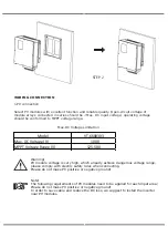
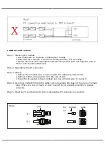


DRM CONNECTION
DRM is provided to support several demand response modes by emitting control signals as
below.
Note: Only PIN6(DRM0) is available now, and other PIN functions are being developed.
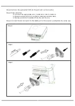
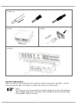
DRM CONNECTION STEPS
Please refer to BMS connection steps (page32) for DRM connection. Please kindly noted
the PIN definition and port position will be slightly different.
DRM
CT
Dry contact
BMS-485
BMS-CAN
Parallel
NTC
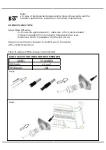
Step 3
Step 4
1
2
3
4
5
6
7
8
DRM1/5
DRM2/6
DRM3/7
DRM4/8
+5V
DRM0
GND
GND
1
8
The seal is used for waterproof. Please make sure it has been kept back.
Step 1, 2
Summary of Contents for VT-6608303
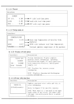
Page 33: ...8 1 7 Grid connected output 8 1 8 Inverter output 8 1 9 Load 8 1 10 Power...
Page 34: ...8 1 11 Power 8 1 12 Temperature 8 1 13 Status information 8 1 14 Error information...
Page 36: ...8 2 Setting 8 2 1 System setting...
Page 37: ......
Page 38: ......
Page 39: ...8 2 2 BAT Setting...
Page 40: ......
Page 41: ...8 2 3 Grid standard...
Page 42: ...8 2 4 System setting...
Page 43: ......
Page 44: ......
Page 45: ...8 2 5 485 Address 8 2 6 485 Baud rate 8 2 7 Language...
Page 46: ...8 2 8 LCD backlight 8 2 9 Date time 8 2 10 Clear history...
Page 47: ...8 2 11 Password Setting 8 2 12 Maintenance 8 2 13 Factory reset 8 2 14 Inquiry...
Page 48: ......
Page 49: ...8 2 12 Statistics...
Page 50: ......
Page 52: ......
Page 53: ......
Page 54: ......


