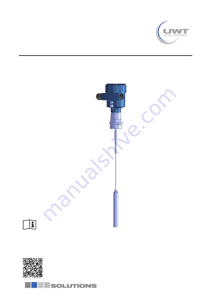
Nivo®Guide 3100
Two-wire 4 … 20 mA/HARTRod and cable probeTDR sensor for continuous level measurement of bulk
solids
Quick setup guide
Document ID: 61268
Page 1: ...Nivo Guide 3100 Two wire 4 20 mA HART Rod and cable probe TDR sensor for continuous level measurement of bulk solids Quick setup guide Document ID 61268 ...
Page 2: ... 4 2 Wiring plan single chamber housing 11 4 3 Wiring plan double chamber housing 11 5 Set up with the display and adjustment module 13 5 1 Insert display and adjustment module 13 5 2 Parameter adjustment Quick setup 14 6 Supplement 16 6 1 Technical data 16 Information This quick setup guide enables quick setup and commissioning of your instrument ÇÍ Æ ŲÆ ÍÊÌÀ Ê ÁÆ ÇÊÅ ÌÁÇÆ ÁÆ ÌÀ ÇÊÊ ËÈÇÆ ÁÆ Ɠ ÇÅÈ...
Page 3: ...ll prevailing regulations and directives The instrument must only be operated in a Ì ÀÆÁ ÄÄÑ Ŵ ÏÄ ËË Æ Ê ÄÁ ºÄ ÇÆ ÁÌÁÇÆƖ À ÇÈ Ê ÌÇÊ ÁË Ê ËÈÇÆËÁ ble for the trouble free operation of the instrument When measuring aggressive or corrosive media that can cause a dangerous situation if the instrument malfunctions the operator has to implement suitable measures to make sure the instrument is functioning...
Page 4: ...automation technology user association in the process industry in Germany The published NAMUR recommendations are ÈÌ Ë ÌÀ ËÌ Æ Ê ÁÆ Ų Ä ÁÆËÌÊÍÅ ÆÌ ÌÁÇÆƖ À ÎÁ ÍÄŲÄË ÌÀ Ê ÉÍÁÊ Å ÆÌË Ç ÌÀ ÇÄÄÇÏÁÆ Ê ÇÅ mendations NE 21 Electromagnetic compatibility of equipment NE 43 Signal level for fault information from measuring transduc ers ˀ Ʊ ÇÅÈ ÌÁºÁÄÁÌÑ Ç Ų Ä ÎÁ Ë Æ ÁËÈÄ ÑƯ ÂÍËÌÅ ÆÌ components ʾʽ Ʊ Ä ƘÅÇÆÁÌÇÊ...
Page 5: ...he type label example 1 Instrument type 2 Product code 3 Approvals option 4 Power supply and signal output electronics 5 Protection rating 6 Probe length measurement accuracy optional 7 Process and ambient temperature process pressure 8 Material wetted parts 9 Order number 10 Serial number of the instrument 11 Symbol of the device protection class 12 ID numbers instrument documentation ʾˀ Á ÆÌÁŲ Ì...
Page 6: ... Å ÌË ÌÀ ÐÁËÌÁÆ ÅºÁ ÆÌ ÇÆ ÁÌÁÇÆËƖ 3 2 Mounting instructions Mount NivoGuide 3100 in such a way that the distance to vessel installations or to the vessel wall is at least 300 mm 12 in In non metallic vessels the distance to the vessel wall should be at least 500 mm 19 7 in During operation the probe must not touch any installations or the vessel wall If necessary fasten the probe end In vessels wi...
Page 7: ...e probes without metal vessel wall e g in plastic Î ËË ÄËƓ ÌÀ Å ËÍÊ Î ÄÍ Æ º ÁÆŴÍ Æ ºÑ ËÌÊÇÆ Ä ÌÊÇÅ Æ ÌÁ Ų Ä Ë Ƽ ÅÁÌÌ ÁÆÌ Ê Ê Æ ÇÊ ÁÆ ÌÇ ʾˀʿ ƕ Ä ËË ƽƖ Ë ÈÊǺ ÁÆ Ç Ð Î ÊËÁÇÆ ÇÊ ÈÈÄÁ ÌÁÇÆË ÁÆ ÄÁÉÍÁ ËƖ 1 2 Fig 3 Mounting in non metallic vessel 1 Flange 2 Metal sheet Concrete vessel When mounting in thick concrete ceilings NivoGuide 3100 should be ÅÇÍÆÌ ÊÇÆÌ ŴÍËÀ ÌÇ ÌÀ ÄÇÏ Ê Ɩ Æ ÇÆ Ê Ì ËÁÄÇËƓ ÌÀ ÁËÌ Æ...
Page 8: ...meter Higher sockets or sockets with a bigger diameter can generally be used They can however increase the upper blocking distance dead band Check if this is relevant for your measurement In such cases always carry out a false signal suppression after ÅÇÍÆÌÁÆ Ɩ ÇÍ Æ ŲÆ ÍÊÌÀ Ê ÁÆ ÇÊÅ ÌÁÇÆ ÍÆ Ê ͷSetup procedure 2 1 1 2 1 1 1 Fig 5 Mounting socket À Æ Ï Ä ÁÆ ÌÀ ËÇ Ã ÌƓ Å Ã ËÍÊ ÌÀ Ì ÌÀ ËÇ Ã Ì ÁË ŴÍËÀ ...
Page 9: ...9 Nivo Guide 3100 Two wire 4 20 mA HART 3 Mounting 61268 EN 190215 1 2 Á Ɩ ƕ Ç Ã Ì ÅÍËÌ º ÁÆËÌ ÄÄ ŴÍËÀ 1 Unfavourable mounting ʿ Ç Ã Ì ŴÍËÀ Ƙ ÇÈÌÁÅÍÅ ÅÇÍÆÌÁÆ ...
Page 10: ...e left 3 Loosen compression nut of the cable gland and remove blind plug ˁƖ ÅÇÎ ÈÈÊÇÐƖ ʾʽ Å Ƽˁ ÁÆƽ Ç ÌÀ ºÄ Å ÆÌÄ Ɠ ËÌÊÁÈ ÈÈÊÇÐƖ 1 cm 0 4 in of insulation from the ends of the individual wires 5 Insert the cable into the sensor through the cable entry 1 2 Fig 7 Connection steps 5 and 6 1 Single chamber housing 2 Double chamber housing 6 Insert the wire ends into the terminals according to the wirin...
Page 11: ... housing lid back on À Ä ÌÊÁ Ä ÇÆÆ ÌÁÇÆ ÁË ŲÆÁËÀ Ɩ 4 2 Wiring plan single chamber housing À ÇÄÄÇÏÁÆ ÁÄÄÍËÌÊ ÌÁÇÆ ÈÈÄÁ Ë ÌÇ ÌÀ ÆÇÆƘ ÐƓ ÐƘÁ Æ ÐƘ ƘÁ version 5 1 2 6 7 8 4 20mA 2 3 4 1 Fig 8 Electronics and connection compartment single chamber housing 1 Voltage supply signal output 2 For display and adjustment module or interface adapter 3 For external display and adjustment unit 4 Ground terminal fo...
Page 12: ...2 6 7 8 4 20mA Display 2 3 4 1 Fig 9 Connection compartment double chamber housing 1 Voltage supply signal output 2 For display and adjustment module or interface adapter 3 For external display and adjustment unit 4 Ground terminal for connection of the cable screening Connection compartment ...
Page 13: ...0 It is not necessary to interrupt the power supply Proceed as follows 1 Unscrew the housing lid 2 Place the display and adjustment module on the electronics in the desired position and turn it to the right until it snaps in 3 Screw housing lid with inspection window tightly back on Disassembly is carried out in reverse order The display and adjustment module is powered by the sensor an ad ditiona...
Page 14: ...lass is required 5 2 Parameter adjustment Quick setup To quickly and easily adapt the sensor to the application select the menu item Quick setup in the start graphic on the display and adjustment module ÇÍ Æ ŲÆ ͷExtended adjustment in the detailed operating instructions Measurement loop name Æ ÌÀ ŲÊËÌ Å ÆÍ ÁÌ Å ÑÇÍ Æ ËËÁ Æ ËÍÁÌ ºÄ Å ËÍÊ Å ÆÌ ÄÇÇÈ Æ Å Ɩ ÇÍ Æ ÆÌ Ê Æ Å ÏÁÌÀ Å ÐƖ ʾˆ À Ê Ì ÊËƖ Type of ...
Page 15: ...ËÌ ÄÁ º ÄÇÏ ÌÀ º Æ Ɩ Min adjustment In this menu item you can enter the min adjustment for the level Enter the suitable distance value in m for the empty vessel e g ÁËÌ Æ ÊÇÅ ÌÀ Ŵ Æ ÌÇ ÌÀ ÈÊǺ Æ ƽ ÇÊÊ ËÈÇÆ ÁÆ ÌÇ ÌÀ È Ê centage value The distance refers tot he sensor reference plane seal ËÍÊ Ç ÌÀ ÈÊÇ ËË ŲÌÌÁÆ ƽƖ Linearisation A linearisation is necessary for all vessels in which the vessel volume Ç...
Page 16: ... Ð ºÄÁÆ ÈÄÍ ʿʽ Ð ʾƖ Ʋ NPT ʾ Ð ºÄÁÆ ÈÄÍ Ɠ ʾ Ð ÄÇËÁÆ È ƼÊ ƽ Wire cross section spring loaded terminals Ʋ Massive wire stranded wire 0 2 2 5 mm AWG 24 14 Ʋ Stranded wire with end sleeve 0 2 1 5 mm AWG 24 16 Voltage supply Operating voltage UB Ʋ ÇÆƘ Ð ÁÆËÌÊÍÅ ÆÌ 9 6 35 V DC Ʋ ÐƘÁ ÁÆËÌÊÍÅ ÆÌ 9 6 30 V DC Operating voltage UB with lighting switched on Ʋ ÇÆƘ Ð ÁÆËÌÊÍÅ ÆÌ 16 35 V DC Ʋ ÐƘÁ ÁÆËÌÊÍÅ ÆÌ 16 30 ...
Page 17: ...al use and operat ing conditions of the sensors and processing systems correspond to the information available at the time of printing Subject to change without prior notice Technical support Please contact your local sales partner address at www uwt de Otherwise please contact us Phone 49 831 57123 0 Fax 49 831 76879 info uwt de www uwt de ...