background image

25

®

1

2 3

4

5

6

7

8

12

11

12

13

14
15

17

16

18

19

20

21

22

23

24

25

9

10

1169 0794 FP

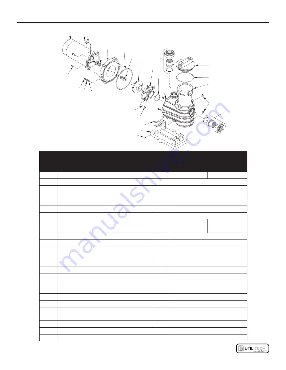
rEplACEmEnT pArTS liST

pArT

dESCripTion

QTY.

pArT # (BY modEl)

uT1100igpp 

1 Hp

uT11501igpp 

1-1/2 Hp

1

Motor, 115/230 V, 1 Phase

1

A100ELL

A100FLL

2

Screw #10-32x1/2 in.

1

U30-692SS

3

Bonding Lug

1

U17-568

4

Slinger

1

17351-0009

5

Seal Plate

1

C3-184P

6

Seal Plate Cord Ring

1

U9-373

7

Shaft Seal

1

37400-0027S

8

Impeller*

1

C105-236P

C105-236PB

9

Diffuser

1

C1-270PB

C1-270PC

10 Diffuser O-ring

1

U9-374

11

Pump and Trap Body (Only)

1

C76-58P

12 2x1-1/2 in. Quick Connect Half Union

2

77703-0101

13 Trap Cover*

1

C3-185P

14 Trap Cover O-ring

1

U9-375

15 Trap Basket

1

C8-58P

16 Drain Plug

2

U178-920P

17 Mounting Screw 5/16 in.-14x5/8 in.

2

U30-919SS

18 Base

1

C4-77P

19 Motor Pad

1

C35-45

20 Screw #8-32x7/8 in. Rd. Hd.

7

U30-542SS

21 Lock Washer #8 Ext. Tooth

7

U43-21SS

22 Flat Washer 3/8 in.

6

U43-62SS

23 Lock Washer 3/8 in.

6

U43-12SS

24 Nut 3/8-16 Hex

6

U36-38SS

25 Cap Screws 3/8 in.-16x1 in. Hex.

4

U30-74SS

* For installations using biguanide sanitizers, order Part No. C3-185P3.

Summary of Contents for 0240058

Page 1: ... a registered trademark of LF LLC All rights reserved Questions problems missing parts Before returning to your retailer call our customer service department at 1 866 994 4148 8 a m 8 p m EST Monday Friday UT243 AB12367 ATTACH YOUR RECEIPT HERE 1916 0895 C IMPORTANT SAFETY INSTRUCTIONS READ AND FOLLOW ALL INSTRUCTIONS SAVE THESE INSTRUCTIONS ...

Page 2: ...OF CONTENTS Package Contents 3 Hardware Contents 4 Safety Information 5 Preparation 8 Installation Instructions 9 Operating Instructions 16 Care and Maintenance 17 Troubleshooting 21 Warranty 23 Replacement Parts List 24 ...

Page 3: ...B Motor 1 C Bonding lug 1 D Slinger 1 E Seal plate 1 F Seal plate O ring 1 G Shaft seal 1 H Impeller 1 I Diffuser 1 J Diffuser O ring 1 K Discharge port 1 L Trap cover 1 M Trap cover O ring 1 N Trap basket 1 O Drain plugs 2 P Suction port 1 Q Base 1 Unit comes preassembled Q A B C D E G F H I K J ...

Page 4: ...4 Lowes com HARDWARE CONTENTS shown actual size 6684 0912 Quick connect half union Qty 2 AA ...

Page 5: ... serious bodily injury or death This pump should be installed and serviced only by a qualified pool service professional Installers pool operators and owners must read these warnings and all instructions in the owner s manual before using this pump These warnings and the owner s manual must be left with pool owner For information about the Virginia Graeme Baker Pool and Spa Safety Act contact the ...

Page 6: ...suction cover must be used for each drain Suction main drain covers must be installed at least 3 ft apart as measured from center to center of the main drain covers Regularly inspect all covers for cracks damage and advanced weathering If a cover becomes loose cracked damaged broken or is missing close the pool or spa immediately shut off the pump post a NOTICE and keep the pool or spa closed unti...

Page 7: ...ystem Remove and replace trap cover Hand tighten trap cover only NOTICE These testing parameters apply only to the models described herein For other equipment consult the manufacturer Hazardous pressure Stand clear of pump and filter not included during start up Pool and spa circulation systems operate under high pressure When any part of the circulation system i e filter locking ring pump filter ...

Page 8: ...missing or damaged do not attempt to install the product Estimated Installation Time 90 minutes Tools Required for Installation not included Pipe Wrench Phillips Screwdriver Flathead Screwdriver PTFE Pipe Thread Sealant PVC Glue Tongue and Groove Pliers Round File or Sandpaper Shut off Valve 1 1 2 in or 2 in Threaded Connections Tape Measure PREPARATION ...

Page 9: ...imers and control systems etc should be properly installed to allow the operation start up shut down or servicing of any pump or filter without requiring the user to place any portion of his her body over or near the pump trap cover or filter lid Such installation should allow the user to stand clear of the filter and pump during system start up shut down or servicing of the system Risk of electri...

Page 10: ...low glue manufacturer s instructions regarding ventilation and fire hazards Union collar connections to pump should be assembled dry and hand tightened NOTICE Pump suction and discharge connections have molded in thread stops DO NOT screw pipe in beyond these stops Pipe thread sealant tape PTFE instructions Use only new or clean PVC pipe fittings Wrap male pipe threads with one to two layers of PT...

Page 11: ...erty damage or death Motors run at high temperatures To reduce the risk of fire do not allow leaves debris or foreign matter to collect around the pump motor To avoid burns when handling the motor let it cool for 20 minutes before trying to work on it Piping Use at least 1 1 2 in 38 mm pipe not included use 2 in 51 mm pipe if possible Increase size if a long run is needed When using 1 1 2 in pipe ...

Page 12: ...p suction system must provide protection against the hazard of suction entrapment or hair entrapment entanglement See Figure 3 Suction Outlet Covers All suction outlet covers not included must be maintained They must be replaced if cracked broken or missing See Testing and Certification for outlet cover certification requirements All suction outlets must have correctly installed screw fastened cov...

Page 13: ... outlet complies with the latest ASME ANSI specification for Suction Fittings For Use in Swimming Pools Spas Hot Tubs and Whirlpool Bathtub Applications In any case do not exceed the suction fitting s maximum designed flow rate If 100 of the pump s flow comes from the main drain system the maximum water velocity in the pump suction hydraulic system must be 6 ft per second or less even if one main ...

Page 14: ... more than 10 above or below motor nameplate rated voltage or motor may overheat causing overload tripping and reduced component life If voltage is less than 90 or more than 110 of rated voltage when motor is running at full load consult power company Grounding Bonding Risk of explosion May cause risk of fire separation severe bodily injury and or property damage Do not ground to a gas supply line...

Page 15: ... load circuit breaker as the master on off switch Install a GFCI or Ground Fault Circuit Interrupter not included in circuit it will sense a short circuit to ground and disconnect power before it becomes dangerous to pool users For size of GFCI required and test procedures see GFCI manufacturer s instructions In case of power outage check GFCI for tripping which will prevent normal pump operation ...

Page 16: ...the motor let it cool for 20 minutes before trying to work on it An automatic internal cutoff switch protects the motor from heat damage during operation Hazardous Suction Can trap hair or body causing severe injury or death Do not block suction Keep small children under close adult supervision at all times 4078 1001 IG Priming the Pump Release all pressure from filter pump and piping system see t...

Page 17: ...will damage pump and void warranty NOTICE Do not use anti freeze solutions except propylene glycol in your pool spa system Propylene glycol or RV antifreeze is non toxic and will not damage plastic system components Other anti freeze formulas are highly toxic and may damage plastic components in the system Drain all water from pump and piping when expecting freezing temperatures or when storing pu...

Page 18: ...use wrenches or any other tools If pump mount is not anchored use caution to avoid breaking attached piping 5 Be sure motor is kept dry and covered Winterized Equipment Startup 1 Remove any temporary weather protection placed around system for shutdown 2 Follow filter manufacturer s instructions for reactivation of the filter 3 Inspect all electrical wiring for damage or deterioration over the shu...

Page 19: ... return piping are closed Release all pressure by opening all vents 1 Drain pump by removing drain plugs O on pump body and trap body See Figure 10 2 Be sure there is no pressure in trap body remove trap cover L by turning counterclockwise 3 Remove six nuts lock washers and flat washers holding seal plate E to pump body See Figure 12 Pull seal plate and motor away from pump body You may have to CA...

Page 20: ...ssure Be sure you do not scratch or nick the seal face See Figure 17 2 If ceramic seat will not locate properly remove it place face up on bench and reclean cavity Ceramic seat should now locate 3 If seat still will not locate properly place a cardboard washer not included over the polished face and use a piece of 3 4 in 19 mm standard pipe not included for pressing purposes NOTICE Be sure not to ...

Page 21: ...user I on seal plate E torque screws to 10 14 in lbs 11 2 16 1 kg cm Install new diffuser O ring J on diffuser 10 Install new seal plate O ring F on the seal plate See Figure 17 Assemble motor and seal plate to pump body K with nuts flat washers and lock washers Torque nuts to 120 130 in lbs 138 150 kg cm 11 Prime pump according to instructions in Priming the Pump Polished surface Rubber surface 3...

Page 22: ...Seal check impeller for clogging follow instructions in Install New Seal for reassembly Impeller and diffuser may be worn If so order replacement parts See Replacement Parts List Failure to pump reduced capacity or discharge pressure Pump may be running too slowly Check voltage at motor terminals and at meter while pump is running If low see wiring instructions or consult power company Check for l...

Page 23: ...ely supported pump assembly will be strained See Installation Instructions Pump not mounted solidly Do not mount pump on a wooden platform Securely mount on concrete platform for quietest performance Cavitation Pump could be cavitating sucking air make sure inlet piping is in water unobstructed and that the pump is not trying to lift water more than 10 ft TROUBLESHOOTING ...

Page 24: ... is not transferable and does not apply to products used in commercial rental applications Sewage Pumps DO NOT return a sewage pump that has been installed to your retail store Contact the Manufacturer s Customer Service Sewage pumps that have seen service and been removed carry a contamination hazard with them If your sewage pump has failed Wear rubber gloves when handling the pump For warranty p...

Page 25: ...9 Diffuser 1 C1 270PB C1 270PC 10 Diffuser O ring 1 U9 374 11 Pump and Trap Body Only 1 C76 58P 12 2x1 1 2 in Quick Connect Half Union 2 77703 0101 13 Trap Cover 1 C3 185P 14 Trap Cover O ring 1 U9 375 15 Trap Basket 1 C8 58P 16 Drain Plug 2 U178 920P 17 Mounting Screw 5 16 in 14x5 8 in 2 U30 919SS 18 Base 1 C4 77P 19 Motor Pad 1 C35 45 20 Screw 8 32x7 8 in Rd Hd 7 U30 542SS 21 Lock Washer 8 Ext T...

Page 26: ...26 Lowes com Printed in U S A Utilitech UT Design is a registered trademark of LF LLC All rights reserved ...

Page 27: ...servados Preguntas problemas piezas faltantes Antes de volver a la tienda llame a nuestro Departamento de Servicio al Cliente al 1 866 994 4148 de lunes a viernes de 8 a m a 8 p m hora estándar del Este UT243 1916 0895 C INSTRUCCIONES IMPORTANTES DE SEGURIDAD LEA Y SIGA TODAS LAS INSTRUCCIONES GUARDE ESTAS INSTRUCCIONES Código de fecha Fecha de compra ADJUNTE SU RECIBO AQUÍ ...

Page 28: ...el paquete 29 Aditamentos 30 Información de seguridad 31 Preparación 34 Instrucciones de instalación 35 Instrucciones de funcionamiento 42 Cuidado y mantenimiento 43 Solución de problemas 48 Garantía 50 Lista de piezas de repuesto 51 ...

Page 29: ...lo 1 E Placa del sello 1 F Junta tórica de la placa del sello 1 G Sello del eje 1 H Impulsor 1 I Difusor 1 J Junta tórica del difusor 1 K Puerto de descarga 1 L Cubierta del sifón 1 M Junta tórica de la cubierta del sifón 1 N Cesta del sifón 1 O Tapones de drenaje 2 P Puerto de succión 1 Q Base 1 La unidad viene preensamblada Q A B C D E G F H I K J ...

Page 30: ...30 Lowes com ADITAMENTOS se muestran en tamaño real 6684 0912 Media unión de conexión rápida Cant 2 AA ...

Page 31: ...e Solo un profesional de servicio de piscinas calificado puede instalar o reparar esta bomba Los instaladores operadores de la piscina y propietarios deben leer estas advertencias y todas las instrucciones del manual del propietario antes de usar esta bomba Estas advertencias y el manual del propietario deben permanecer con el propietario de la piscina Para obtener más información sobre la Ley de ...

Page 32: ...renaje Las cubiertas del drenaje de succión principal se deben instalar al menos a 91 44 cm de distancia medido de centro a centro de las cubiertas del drenaje principal Inspeccione regularmente todas las cubiertas para verificar que no tengan grietas daños ni desgaste por condiciones climáticas Si una cubierta se suelta agrieta daña rompe o falta cierre la piscina o spa inmediatamente apague la b...

Page 33: ...re y reemplace la cubierta del sifón Apriete la cubierta del sifón a mano solamente AVISO Estos parámetros de prueba se aplican solo a los modelos descritos en este documento Para otros equipos consulte con el fabricante Presión peligrosa Mantenga la distancia de la bomba y el filtro no se incluye durante el arranque Los sistemas de circulación de piscinas y spas funcionan con alta presión Cuando ...

Page 34: ...lguna pieza o si estas están dañadas Tiempo estimado de instalación 90 minutos Herramientas necesarias para la instalación no incluidas Llave para tubos destornillador Phillips destornillador de cabeza plana cinta selladora para roscas de PTFE adhesivo para PVC pinzas de ranura y lengüeta lima redonda o papel de lija válvula de cierre conexiones roscadas de 1 1 2 pulg o 2 pulg cinta métrica Prepar...

Page 35: ...omba u otro componente del sistema Los controles eléctricos como los interruptores de encendido apagado temporizadores y sistemas de control etc se deben instalar adecuadamente para permitir la operación arranque apagado o servicio de cualquier bomba o filtro sin requerir que el usuario coloque cualquier parte de su cuerpo sobre o cerca de la cubierta del sifón de la bomba o la tapa del filtro Dic...

Page 36: ...as en algunos plásticos y puede dañar los componentes del sistema de tuberías Al conectar el tubo a la bomba con la media unión de conexión rápida AA siga las instrucciones del fabricante de adhesivo con respecto a la ventilación y los peligros de incendio Las conexiones de aro de unión a la bomba se deben ensamblar en seco y apretar a mano AVISO Las conexiones de succión y descarga tienen topes r...

Page 37: ...nto a la bomba y los tubos Riesgo de incendio y quemaduras Puede causar lesiones graves daños a la propiedad o la muerte Los motores funcionan a altas temperaturas Para disminuir el riesgo de incendio no permita que se acumulen hojas desechos o sustancias extrañas cerca del motor de la bomba Para evitar quemaduras al manipular el motor déjelo enfriar durante 20 minutos antes de trabajar en él Las ...

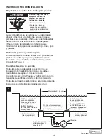
Page 38: ...n para los requisitos de certificación de las cubiertas de salida Todas las salidas de succión deben estar correctamente instaladas con cubiertas atornilladas en su luar Minimum of 3 ft Suction outlet main drain Suction outlet main drain IAPMO certified anti entrapment cover or suction fitting screw fastened to main drain sump IAPMO certified anti entrapment cover or suction fitting screw fastened...

Page 39: ... ANSI para Conectores de succión para usar en aplicaciones de piscinas spas jacuzzis y tinas de hidromasaje En cualquier caso no exceda el caudal de flujo máximo designado del conector de succión Si el 100 del flujo de la bomba viene del sistema de drenaje principal la velocidad de agua máxima del sistema hidráulico de succión de la bomba debe ser de 1 83 m por segundo o menos incluso si un drenaj...

Page 40: ...un apagado por sobrecarga y una menor vida útil del componente Si el voltaje es menor a 90 o de más de 110 del voltaje clasificado cuando el motor está funcionando a carga completa consulte con la compañía de electricidad Puesta a tierra adhesión Riesgo de explosión Podría causar un riesgo de incendio separación lesiones corporales graves y o daños a la propiedad No conecte a tierra en una línea d...

Page 41: ...nterruptor de circuito de falla de puesta a tierra no se incluye en el circuito percibirá un cortocircuito en la conexión a tierra y desconectará la alimentación antes de que se vuelva peligroso para los usuarios de la piscina Consulte las instrucciones del fabricante para obtener información sobre el tamaño de GFCI requerido y los procedimientos de prueba de GFCI En caso de un corte de electricid...

Page 42: ... al manipular el motor déjelo enfriar durante 20 minutos antes de trabajar en él Un interruptor de corte interno automático protege al motor de los daños por calor durante la operación Hazardous Suction Can trap hair or body causing severe injury or death Do not block suction Keep small children under close adult supervision at all times 4078 1001 IG Cebado de la bomba Libere toda la presión del f...

Page 43: ...lución de problemas Cuidado y mantenimiento Almacenaje preparación para el invierno AVISO Al permitir que se congele la bomba esta se dañará y se anulará la garantía AVISO No use soluciones anticongelantes excepto propilenglicol en el sistema de piscina spa El propilenglicol o anticongelante RV no es tóxico y no dañará los componentes plásticos del sistema Otras fórmulas anticongelantes son altame...

Page 44: ...te vuelva a colocar la cubierta del sifón AVISO Apriete la cubierta del sifón solo con la mano No use llaves ni ninguna otra herramienta Si el montaje de la bomba no está anclado tenga cuidado para evitar romper la tubería fija 5 Asegúrese de que el motor se mantenga seco y cubierto Arranque de equipos con preparación para el invierno 1 Retire cualquier protección climática provisoria colocada alr...

Page 45: ...esconecte la alimentación del motor de la bomba Asegúrese de que las válvulas de compuerta de los tubos de succión y retorno estén cerradas Libere toda la presión abriendo todas las ventilaciones 1 Drene la bomba removiendo los tapones de drenaje O en el cuerpo de la bomba y el cuerpo del sifón Consulte la Figura 10 2 Asegúrese de que no haya presión en el cuerpo del sifón retire la cubierta L gir...

Page 46: ...con una pequeña cantidad de detergente líquido no se incluye presione el nuevo asiento de cerámica en la cavidad de la placa del sello firmemente y a escuadra con la presión de los dedos Asegúrese de no rayar ni perforar la superficie del sello Consulte la Figura 17 2 Si el asiento de cerámica no se ubica adecuadamente retírelo colóquelo hacia arriba en una banca y vuelva a limpiar la cavidad Ahor...

Page 47: ...a del sello 9 Monte el difusor I en la placa del sello E ajuste el torque de los tornillos en 1 15 a 1 61 kg m 10a 14 pulg lb Instale la nueva junta tórica del difusor J en el difusor 10 Instale la nueva junta tórica de la placa del sello F en la placa del sello Consulte la Figura 17 Ensamble el motor y la placa del sello en el cuerpo de la bomba K con tuercas arandelas planas y arandelas de segur...

Page 48: ... que el impulsor no esté obstruido Siga las instrucciones en Reemplazo del sello existente verifique que el impulsor no esté obstruido siga las instrucciones en Instalación del nuevo sello para volver a ensamblar Es posible que el impulsor y el difusor estén desgastados De ser así pida piezas de repuesto Consulte la Lista de piezas de repuesto Falla al bombear capacidad disminuida o menor presión ...

Page 49: ...bomba o los tubos no cuentan con el soporte adecuado Si las tuberías de succión y descarga no cuentan con un soporte adecuado habrá tensión en la unidad de la bomba Consulte las instrucciones de instalación La bomba no está montada firmemente No monte la bomba en una plataforma de madera Monte en forma segura en una plataforma de concreto para un rendimiento más silencioso Cavitación La bomba podr...

Page 50: ...e la garantía La garantía no es transferible y no cubre todos los productos utilizados en aplicaciones comerciales o de alquiler Bombas para aguas servidas NO devuelva la bomba para aguas servidas que se ha instalado a la tienda minorista Póngase en contacto con el Servicio al Cliente del Fabricante Las bombas para aguas servidas que se han reparado y retirado conllevan un peligro de contaminación...

Page 51: ...76 58P 12 Media unión de conexión rápida de 2x1 1 2 pulg 2 77703 0101 13 Cubierta del sifón 1 C3 185P 14 Junta tórica de la cubierta del sifón 1 U9 375 15 Cesta del sifón 1 C8 58P 16 Tapón de drenaje 2 U178 920P 17 Tornillo de montaje de 5 16 pulg a 14x5 8 pulg 2 U30 919SS 18 Base 1 C4 77P 19 Almohadilla del motor 1 C35 45 20 Tornillo 8 32x7 8 pulg de cabeza redonda 7 U30 542SS 21 Arandela de segu...

Page 52: ...52 Lowes com Impreso en EE UU Utilitech UT Design es una marca registrada de LF LLC Todos los derechos reservados ...

Reviews: