


GAS COMPRESSORS / BOOSTERS
GAS & AIR MIXING SYSTEMS
AIR BLOWERS & VACUUM PUMPS
The Utile Engineering Co. Ltd.
Irthlingborough, Northamptonshire, NN9 5UG, ENGLAND
Telephone: + 44 (0) 1933 650216 Facsimile: + 44 (0) 1933 652738 Email: [email protected]
www.utileengineering.com
Feb-19
10
IC013 Rev2
Fitting Pulleys and Couplings
These should be bored to our standard limits (details supplied upon request) and fitted to the shaft with a screwing motion. On no
account should they be driven on. Tapping of fitments onto the machine shaft with a hammer or mallet, causes bearing damage. This
results in an increase in bearing noise and a significant reduction in bearing life. Attention should be paid to the guarding of all moving
parts.
Drive Bushes
Ensure that all mating surfaces are completely clean and free from oil and dirt. Lightly oil the grub screw thread and tip of grub screw.
Using a hexagon wrench to tighten to the torques shown below.
Bush size
1008
1108
1210
1610
1615
2012
2517
3020
3030
3525
3535
Tightening Torque (Nm)
5.6
5.6
20
20
20
30
50
90
90
115
115
Screw
Details
Qty
2
2
2
2
2
2
2
2
2
3
3
Size (BSW)
¼”
¼”
3/8”
3/8”
3/8”
7/16”
½”
5/8”
5/8”
½”
½”
Hex socket size
(mm)
3
3
5
5
5
6
6
8
8
10
10
Drive Alignment
The compressor/booster must be accurately aligned with the prime mover, failure to maintain this will lead to excessive loads being
placed on the bearings and coupling and cause undue wear of the drive coupling or belts.
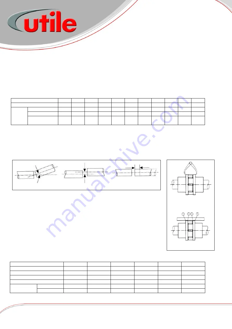
The rotor shaft must always be horizontal. There are three basis modes of misalignment, these are angular, parallel and axial (shown
in fig. 3).
Flexible Coupling
1.
Remove any dirt, oil, etc. from all mating surfaces. Place bush in hub and match half
holes on both shafts.
2.
Place setscrews loosely in threaded holes. Mount assembly in desired position on shafts.
3.
Tighten setscrews. Place disc/flexible coupling in position, and bring the shafts together
obtaining the manufacturers assembled length for the coupling given in their
instructions.
4.
To check for angular alignment: (see fig. 4). Rotate the coupling through 90
°
and
measure the distance between the faces. Repeat adjusting the shafts until four identical
measurements are obtained.
To check for parallel alignment: (see fig. 4). Place a straight edge across the coupling.
The hubs will be in correct alignment when the straight edge contacts the 4 points squarely.
If being installed in a hazardous area, the coupling/spider
must
be inspected after 3000hours or
6 months after start-up. If no significant wear then further inspections at 3000 hourly intervals.
However, if significant wear is noticed it is recommended to replace the spider.
Coupling Size
SPDR70
L090
L100
RFC13FF
RFC15FF
RFC18FF
Utile Part No.
P1017
P1010
P1011
P1146/A
P1436
P1431
Max. Speed
14000
9000
7000
4850
4200
3500
Power (kw) /100rpm
0.05
0.10
0.50
3.30
6.28
9.95
Nominal Torque (Nm)
4.9
16.3
47.1
315
600
950
Max.
Misalignment
Parallel (mm)
0.25
0.40
0.40
0.40
0.40
0.40
Angular
1°
1°
1°
1°
1°
1°
Angular Misalignment
Parallel Misalignment
Axial Misalignment
Fig. 3
Installation - Drive
Parallel Alignment Check
Angular Alignment Check
Fig. 4


