8
BOILER
WATER INLET
ALTERNATE
CIRCULATOR
LOCATION
TO SYSTEM
FROM SYSTEM
CIRCULATOR
SHUT-OFF
VALVE
PRESSURE
REDUCER VALVE
CHECK VALVE
BALL VALVE
3 WAY MIXING
VALVE
AIR SEPARATOR
HOSE BIB
EXPANSION
TANK
7.
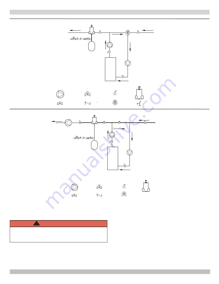
Installation using circulators and zone valves are
shown in Figures 8-11. For further piping information
refer to I=B=R Installation and Piping Guide.
WARNING
Burn and scald hazard. Safety relief valve could
discharge steam or hot water during operation.
Install discharge piping per these instructions.
!
8.
Install discharge piping from safety relief valve.
Use ¾" or larger pipe.
•
Use pipe suitable for temperatures of 375°F (191°C)
•
or greater.
Individual boiler discharge piping shall be independent
•
of other discharge piping.
Size and arrange discharge piping to avoid reducing
•
safety relief valve relieving capacity below minimum
relief valve capacity stated on rating plate.
Run pipe as short and straight as possible to location
•
protecting user from scalding and properly drain
piping.
Install union, if used, close to safety relief valve outlet.
•
Install elbow(s), if used, close to safety relief valve
•
outlet and downstream of union (if used).
Terminate pipe with plain end (not threaded).
•
connectIng supply and return pIpIng
BOILER
ALTERNATE
CIRCULATOR
LOCATION
TO SYSTEM
FROM SYSTEM
V2
V1
CIRCULATOR
SHUT-OFF
VALVE
PRESSURE
REDUCER VALVE
CHECK VALVE
BALL VALVE
AIR SEPARATOR
ZONE VALVE
EXPANSION
TANK
WATER INLET
SYSTEM
CIRCULATOR
Figure 6 - Bypass Piping Automatic Mixing Valve
Figure 7 - Bypass Piping - Fixed Low Temp Only Automatic Mixing Valve


