background image

17

LIGHTING PROCEDURE FOR BOILER WITH 
INTERMITTENT PILOT SYSTEM

For Your Safety, Read Before Operating!!

This appliance is equipped with an ignition device which 

A. 

automatically lights the pilot. Do not try to light the 

appliance by hand.
Before operating, smell all around the appliance area 

B. 

for gas. Be sure to smell next to the floor because 
some gas is heavier than air and will settle on the floor.

!


CAUTION

WHAT TO DO IF YOU SMELL GAS

• Do not try to light any appliance.
• Do not touch any electrical switch; do not 

use any phone in your building.

• Immediately call your gas supplier from a 

neighbor’s phone. Follow the gas supplier's 

instructions.

• If you cannot reach your gas supplier, call 

the fire department.

Use only your hand to push in or turn the gas control 

C. 

knob. Never use tools. If the knob will not push in or 

turn by hand, don’t try to repair it. Call a qualified 

service  technician. Force or attempted repair may 

result in a fire or explosion.

Do not use this appliance if any part has been under 

D. 

water. Immediately call a qualified service technician 

to inspect appliance and to replace any part of control 

system and any gas control which has been under 
water.

OPERATING INSTRUCTIONS FOR INTERMITTENT PI-
LOT SYSTEM

STOP! Read the safety information to the left.

1. 

Set the thermostat to lowest setting.

2. 

Turn off all electric power to the appliance.

3. 

This appliance is equipped with an ignition device which 

4. 

automatically lights the pilot. Do not try to light the 
pilot by hand. 

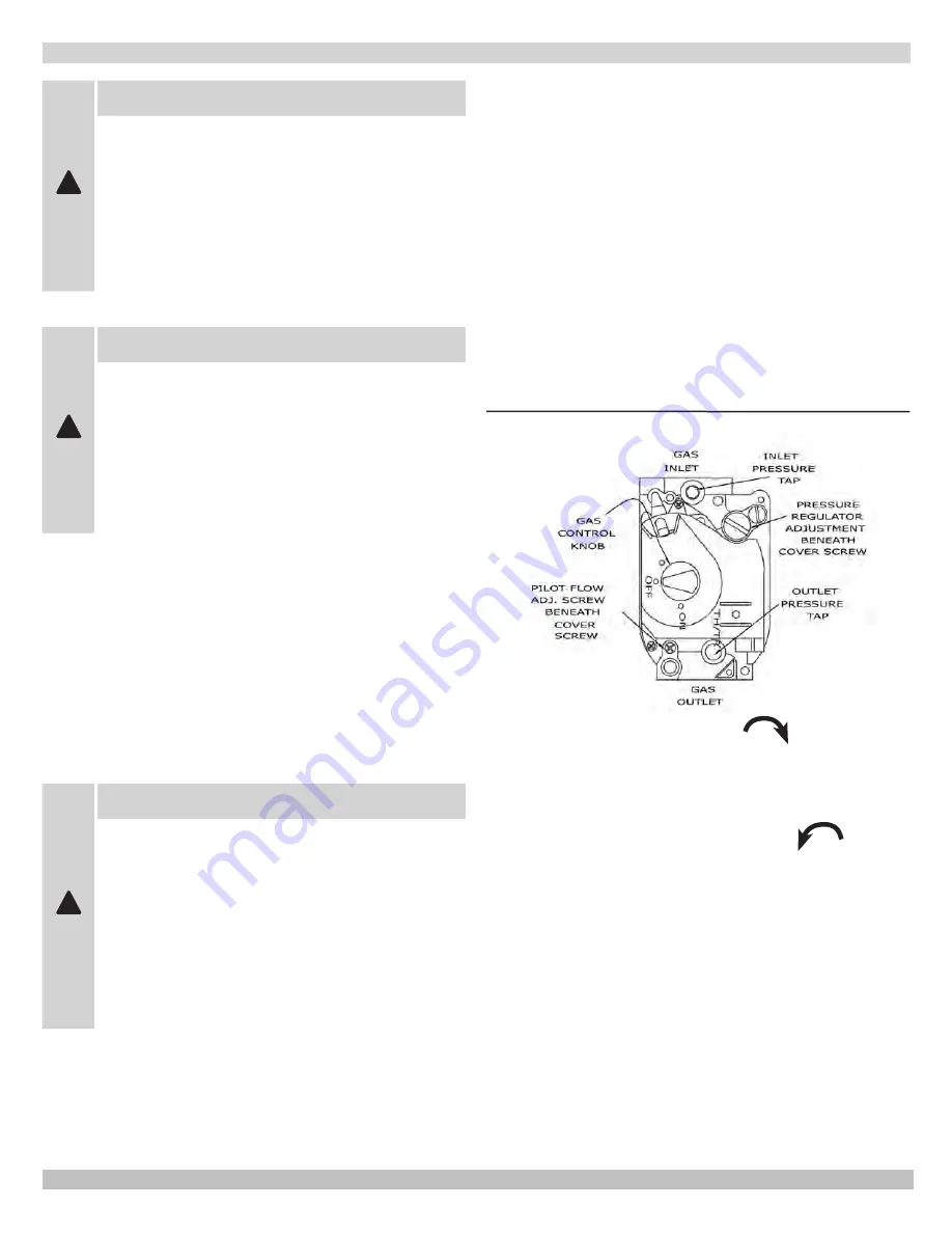
Figure 15 - Intermittent Pilot

Turn gas control knob clockwise 

5. 

 to “OFF.”

Wait (5) minutes to clear out any gas. If you then smell 

6. 

gas, STOP! Follow “What To Do If You Smell Gas” in the 

safety information to the left. If you don’t smell gas, go 

on to the next step.

Turn gas control knob counterclockwise 

7. 

 to “ON.”

Turn on all electric power to the appliance.

8. 

Set thermostat to desired setting.

9. 

If the appliance will not operate, follow the instructions 

10. 

To Turn Off Gas To Appliance

” on next page, and 

call a qualified service technician or your gas supplier.

lIghtIng InstructIons

!


WARNING

If you do not follow these instructions exactly, 

a fire or explosion may result, causing 

property damage, personal injury or loss of 

life.
Before any procedures are attempted on this 

appliance, determine if ignition system is 

electric or standing pilot. If you are uncertain, 

contact manufacturer before proceeding.

!


WARNING

Before lighting any type of pilot burner 

(standing or intermittent), make certain the 

hot water boiler and system are full of water 

to minimum pressure of 12 psi in the system, 

and also verify system is vented of air. Set 

operating control of thermostat to “below” 

normal setting. Refer to following appropriate 

lighting instruction.

Summary of Contents for OMGB Series

Page 1: ... SERIES Cast Iron Gas Fired Boilers For Forced Hot Water INSTALLATION OPERATION MAINTENANCE MANUAL MODEL NUMBERS OMGB50 OMGB75 OMGB100 OMGB125 OMGB150 OMGB175 OMGB200 OMGB250 OMGB300 ECR International 2201 Dwyer Avenue Utica New York 13501 USA www ecrinternational com ...

Page 2: ...ndicates a hazardous situation which if not avoided may result in minor or moderate injury NOTICE Indicates information which should be followed to ensure proper installation and operation WARNING Keep boiler area clear and free from combustible materials gasoline and other flammable vapors and liquids DO NOT obstruct air openings to the boiler room Modification substitution or elimination of fact...

Page 3: ...a level Canada 2000 ft 610m to 4500 1350m above sea level Reduce input per table Canada over 4500 ft 1350m above sea level Contact Provincial authority having jurisdiction 2 Net I B R Water Ratings shown based on piping and pickup allowance of 1 15 Consult manufacturer before selecting boiler for installations having unusual piping and pickup requirements such as intermittent system operation exte...

Page 4: ...pply Return Tappings A B C D E F 50 11 5 4 30 36 6 1 75 15 7 5 30 37 6 1 100 15 7 6 30 37 6 1 125 18 9 6 30 37 6 1 150 18 9 7 30 37 7 1 175 22 11 7 30 38 7 1 200 22 11 8 30 38 8 1 250 26 13 16 13 8 30 40 8 1 300 30 15 9 30 42 10 1 Propane gas inlet all units 1 2 Dimensions ...

Page 5: ... trap control replacement etc Locate boiler on level solid base as near the chimney 6 as possible and centrally located with respect to the heat distribution system as practical Allow 24 inches 610mm at the front and right side for 7 servicing and cleaning When installed in a utility room the door should be 8 wide enough to allow the largest boiler part to enter or to permit replacement of another...

Page 6: ...th outdoors Two Permanent Opening Method Provide opening о о commencing within 12 inches of top and second opening commencing within 12 inches of bottom enclosure Direct communication with outdoors or communicating through vertical ducts Provide minimum free area of 1 in2 per 4 Mbh of total input rating of all appliances in enclosure Communicating through horizontal ducts Provide minimum free area...

Page 7: ... each circulator must be supplied with a flow control valve to prevent gravity circulation Hot water boilers and system must be filled with water 5 and maintained to a minimum pressure of 12 psi Bypass piping is an option which gives the ability to 6 adjust the supply boiler water temperature to fit the system or the condition of the installation This method of piping however is not typically requ...

Page 8: ...iping shall be independent of other discharge piping Size and arrange discharge piping to avoid reducing safety relief valve relieving capacity below minimum relief valve capacity stated on rating plate Run pipe as short and straight as possible to location protecting user from scalding and properly drain piping Install union if used close to safety relief valve outlet Install elbow s if used clos...

Page 9: ...ALVE HOSE BIB FLOW CONTROL VALVE EXPANSION TANK BOILER DHW CIRCULATOR CH CIRCULATOR PRIORITY ZONE CIRCULATOR EXPANSION TANK WATER INLET FLOW CONTROL VAVLE SHUT OFF VALVE PRESSURE REDUCER VALVE CHECK VALVE BALL VALVE AIR SEPARATOR ZONE VALVE HOSE BIB Connecting Supply and Return Piping Figure 8 Single Zone System With DHW Priority Figure 9 Multi Zone System With Circulators And DHW Priority ...

Page 10: ...RIORITY ZONE BOILER WATER INLET CH DHW SYSTEM CIRCULATOR USE FULL PORT ZONE VALVE FOR OPTIMUM TANK PERFORMANCE CONSIDER USING ZONE CIRCULATOR SEE FIGURE 5 ZONE 4 CIRCULATOR SHUT OFF VALVE PRESSURE REDUCER VALVE CHECK VALVE EXPANSION TANK AIR SEPARATOR ZONE VALVE HOSE BIB FLOW CONTROL VALVE Connecting Supply and Return Piping Figure 10 Multi Zone System With Zone Valves And DHW Priority With Circul...

Page 11: ...ING This boiler shall not be connected to any portion of a mechanical draft system operating under positive pressure Vent System Modification REMOVAL OF BOILER FROM VENTING SYSTEM At the time of removal of an existing boiler the following steps shall be followed with each appliance remaining connected to the common venting system placed in operation while the other appliances remaining connected t...

Page 12: ...NS Verify only boiler is serviced by Vent Damper 1 Figure 13 Clearance of not less than 6 inches 152mm between 2 Vent Damper and combustible material must be maintained Additional clearance should be allowed for service of Vent Damper Vent Damper must be in the open position when 3 appliance main burners are operating The Vent Damper position indicator must be in a visible 4 location following ins...

Page 13: ... serious injury Leak Check Gas Piping Pressure test boiler and gas connection before placing boiler in operation Pressure test over 1 2 psig 3 5 kPa Disconnect boiler and its individual gas shutoff valve from gas supply system Pressure test at 1 2 psig 3 5 kPa or less Isolate boiler from gas supply system by closing manual gas shutoff valve Locate leakage using gas detector noncorrosive detection ...

Page 14: ...bove the floor NEVER install a thermostat on an outside wall 2 Do not install a thermostat where it will be affected 3 by drafts hot or cold pipes sunlight lighting fixtures televisions a fireplace or a chimney Check thermostat operation by raising and lowering 4 thermostat setting as required to start and stop the burners Instructions for the final adjustment of the thermostat 5 are packaged with...

Page 15: ...15 VR8200 OR VR8300 Wiring Diagram 24V Standing Pilot ...

Page 16: ...16 Wiring Diagram Intermittent Ignition ...

Page 17: ...on to the left 1 Set the thermostat to lowest setting 2 Turn off all electric power to the appliance 3 This appliance is equipped with an ignition device which 4 automatically lights the pilot Do not try to light the pilot by hand Figure 15 Intermittent Pilot Turn gas control knob clockwise 5 to OFF Wait 5 minutes to clear out any gas If you then smell 6 gas STOP Follow What To Do If You Smell Gas...

Page 18: ...ontrol knobs cannot be turned from PILOT to OFF unless knob is pushed in slightly DO NOT FORCE Wait 5 minutes to clear out any gas If you then smell 6 gas STOP Follow What To Do If You Smell Gas on previous page If you don t smell gas go to the next step Find pilot Follow metal tube from gas control Depend 7 ing on the model of the boiler pilot is either mounted on the base or on one of the burner...

Page 19: ... minimum pressure and open air vents if used to expel any air that may have accumulated in the system Check the entire piping system and if any leaks appear have them repaired Circulators need to be checked and maintained Refer to the circulator manufacturer s instructions The venting system should be inspected at the start of each heating season Check the vent pipe from the boiler to the chimney ...

Page 20: ... flame Be sure to replace cover screw after adjustment to prevent possible gas leakage Figures 15 17 on previous pages The burners and pilot should be checked for signs of corrosion rust or scale buildup The area around the boiler must be kept clear and free of combustible materials gasoline and other flammable vapors and liquids The free flow of combustion and ventilating air to the boiler and bo...

Page 21: ...minus 0 3 inches water column from the specified pressure Primary air adjustment is not necessary therefore air shutters are not furnished as standard equipment Air shutters can be furnished on request where required by local codes or conditions Check Safety Control Circuit Ignition system safety shutoff device must be tested after placing boiler in operation Figures 15 17 on previous pages 1 Pilo...

Page 22: ...VE VR8200H 50 150 24V NAT VG 003 05 1 GAS VALVE VR8200H 50 300 24V LP VG00307 GAS VALVE VR8204H 50 150 SPARK NAT VG01101 GAS VALVE VR8304H4 175 300 SPARK NAT VG01103 GAS VALVE VR8304 50 300 SPARK LP VG01104 GAS VALVE VR8300H4 250 300 24V NAT VG01201 GAS VALVE VR8300H4 175 200 24V NAT VG01202 7 ORIFICE3 2mmNAT 50 100 150 200 250 300 240007406 ORIFICE 3 0mm NAT 175 240007404 ORIFICE 2 9mm NAT 125 24...

Page 23: ...nter Section 175 200 3 Center Section 250 4 Center Section 300 6 Item Part No Description Qty 7 100 2 2 01 Left Hand Section 1 8 43300976 Push Nipple 2 Mach 050 2 Push Nipple 2 Mach 075 100 4 Push Nipple 2 Mach 125 150 6 Push Nipple 2 Mach 175 200 8 Push Nipple 2 Mach 250 10 Push Nipple 2 Mach 300 12 9 3461601 Baffle 075 175 Only 2 Fully Assembled Heat Exchangers 100 2 7 01 Heat Exchanger 3 Sectio...

Page 24: ...3161202 PANEL BASE 125 150 3161203 PANEL BASE 175 200 3161204 PANEL BASE 250 3161205 PANEL BASE 300 3161206 Item DESCRIPTION Part Number Qty 6 PANEL RIGHT 50 200 3162705 1 PANEL RIGHT 225 300 3162703 7 PANEL REAR 50 3162601 1 PANEL REAR 75 100 3162602 PANEL REAR 125 150 3162603 PANEL REAR 175 200 3162604 PANEL REAR 250 3162605 PANEL REAR 300 3162606 8 FLUE COL 50 3462101 1 FLUE COL 100 3462102 FLU...

Page 25: ...LOT 1 240007096 LP Q345A Pilot Included with 3 Pilot Tube Assembly Kit above CONTINUOUS PILOT Item Part No Description Qty 1 109007296 PILOT BRACKET ASSEMBLY 1 2 HW 005 01 BRACKET SCREW 2 3 1520001 THERMOCOUPLE Q309 1 4 14615005 PILOT TUBING 1 8 x 24 1 5 14662098 Natural Gas Q314A PILOT 1 240007285 LP Q314A Pilot Included with 3 Pilot Tube Assembly Kit above 1 1 5 5 3 4 4 2 2 3 Replacement Parts P...

Page 26: ... PIPE TEE 1 1 4X3 4X1 1 4 PF 008 03 1 7 PIPE 1 1 4 CLOSE NPL PF 006 01 1 8 WIRE LOW VOLTAGE DAMPER 375 1 14 01 1 9 HARNESS CIRCULATOR 72 37519501 1 10 CONTROL L8148E1257 AQUASTAT 1010002 1 11 RELIEF VALVE 30 VR 001 01 1 12 WELL 3 4 X3 AQ 020 01 1 13 GAUGE THERALTIMETER GA 001 00 1 14 PIPE NPL 3 4 X4 PF 005 11 1 15 PIPE ELBOW 3 4 90 PF 002 04 1 16 CLAMP 3600 WHITE EF03601 2 17 PLT SPARK CTRL S8600 ...

Page 27: ... SENSOR BRACKET 3262001 1 2 CONTROL FIXED TEMPERATURE THERMO ROLLOUT SWITCH AQ02101 1 3 SCREW 6 X HEX HD HW06501 2 The rollout switch is located on the base and flue collector NOTE The quantities above are for each switch Rollout Spill Switch ...

Page 28: ...ECR International 2201 Dwyer Avenue Utica NY 13501 Phone 315 797 1310 Fax 866 432 7329 e mail info ecrinternational com web site www ecrinternational com ...

Reviews: