background image

6

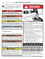
 WARNING

Keep boiler area clear and free from combustible 

materials, gasoline and other flammable vapors and 

liquids.

DO NOT obstruct air openings to the boiler room.

Modification, substitution or elimination of factory 

equipped, supplied or specified components may 

result in personal injury or loss of life.

Installation and service of this boiler shall be performed 

by a qualified installer.

When this product is installed in the Commonwealth 

of Massachusetts the installation shall be performed 

by a Licensed Plumber or Licensed Gas Fitter.

!


 WARNING

Combustion chamber insulation in this product 

contains ceramic fiber material. Ceramic fibers 

can be converted to cristobalite in very high 

temperature applications. The International Agency 

for Research on Cancer (IARC) has concluded, 

Crystalline silica inhaled in the form of quartz 

or cristobalite from occupational sources is 

carcinogenic to humans (Group1). Avoid breathing 

dust and contact with skin and eyes. Use NIOSH 

certified dust respirator (N95). This type of 

respirator is based on the OSHA requirements 

for cristobalite at the time this document was 

written. Other types of respirators may be needed 

depending on the job site conditions. Current 

NIOSH recommendations can be found on the 

NIOSH website

 https://www.cdc.gov/niosh/topics/

silica/.

 NIOSH approved respirators, manufacturers, 

and phone numbers are also listed on this website. 

Wear long-sleeved, loose fitting clothing, gloves, 

and eye protection. Apply enough water to the 

combustion chamber lining to prevent dust. Wash 

potentially contaminated clothes separately from 

other clothing. Rinse clothes washer thoroughly.

NIOSH stated First Aid. Eye: Irrigate immediately. 

Breathing: Fresh air.

!


2 - SAFETY SYMBOLS AND WARNINGS

2.2 For Your Safety 

2.2 For Your Safety 

Manufacturer recommends a carbon monoxide detector 

Manufacturer recommends a carbon monoxide detector 

located on each floor of your home. Follow your detector's 

located on each floor of your home. Follow your detector's 

instructions for operation and verification.  Some 

instructions for operation and verification.  Some 

jurisdictions may, by law, require.

jurisdictions may, by law, require.

WARNING

Fire, Explosion, Asphyxiation, Electrical shock 

hazard! Flooding will result in damages such as 

electrical problems, corrosion, inoperative parts, 

mold and other unforeseen issues which can 

occur over time. Any equipment determined by 

a professional as damaged by a flood, defined as 

excess of water or other liquid, shall be replaced. 

Failure to follow these directions will result in a 

Hazardous Situation.

!


 PN 240012785 Rev. C  [11/15/2020]

Summary of Contents for MGB Series

Page 1: ...NANCE MANUAL Models MGB 060K MGB 095K MGB 120K MGB 150K MGB 175K MGB 205K MGB 235K Manufactured by ECR International Inc 2201 Dwyer Avenue Utica NY 13501 Tel 800 325 5479 www ecrinternational com PN 240012785 REV C 11 15 2020 Tested For 50 psi ASME Working Pressure C S A Certified For Natural Gas Or Propane ...

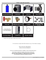
Page 2: ...y for updates www ecrinternational com Information and specifications outlined in this manual in effect at the time of printing of this manual ECR International reserves the right to discontinue change specifications or system design at any time without notice and without incurring any obligation whatsoever Items found in parts box included with your boiler PN 240012785 Rev C 11 15 2020 KEEP THIS ...

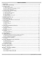
Page 3: ...0 8 Vent Damper Installation Instructions 21 8 1 Vent Damper 21 9 Connecting Gas Service 23 9 1 General 23 9 2 Leak Check Gas Piping 23 10 Electrical 24 10 1 Electrical Wiring 24 10 2 Thermostat Installation 24 11 Wiring Diagrams 25 12 Lighting Instructions 27 12 1 Lighting Procedure For Boiler With Intermittent Pilot System 27 12 2 Operating Instructions For Intermittent Pilot System 27 12 3 To T...

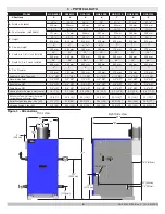
Page 4: ...lue Diameter 4 5 6 6 7 7 7 102 mm 127 mm 152 mm 152 mm 178 mm 178 mm 178 mm Supply Return Tappings 1 1 4 NPT 1 1 4 NPT 1 1 4 NPT 1 1 4 NPT 1 1 4 NPT 1 1 4 NPT 1 1 4 NPT Natural Gas Inlet 1 2 NPT 1 2 NPT 1 2 NPT 1 2 NPT 1 2 NPT 3 4 NPT 3 4 NPT Relief Valve NPT 3 4 NPT 3 4 NPT 3 4 NPT 3 4 NPT 3 4 NPT 3 4 NPT 3 4 NPT Drain Valve NPT 3 4 NPT 3 4 NPT 3 4 NPT 3 4 NPT 3 4 NPT 3 4 NPT 3 4 NPT Heating Wate...

Page 5: ...tand all requirements before beginning installation FOR YOUR SAFETY READ BEFORE OPERATING Hot Water Can Scald Water heated to temperature for clothes washing dish washing and other sanitizing needs can scald and cause permanent injury Children elderly and infirm or physically handicapped persons are more likely to be permanently injured by hot water Never leave them unattended in bathtub or shower...

Page 6: ... Current NIOSH recommendations can be found on the NIOSH website https www cdc gov niosh topics silica NIOSH approved respirators manufacturers and phone numbers are also listed on this website Wear long sleeved loose fitting clothing gloves and eye protection Apply enough water to the combustion chamber lining to prevent dust Wash potentially contaminated clothes separately from other clothing Ri...

Page 7: ...and height 7 Verify floor will support weight of boiler water and equipment 8 Boiler may be installed on combustible floor Do not install boiler on carpeting 9 Do not install where gasoline or other flammable liquids or vapors will be stored or used See Table 3 1 page 8 Contaminants 10 Chimney shall be lined in a manner acceptable to the authority having jurisdiction 11 Garage installation boiler ...

Page 8: ... Acids Solvents etc Paint Varnish Turpentine etc Cleaning Solvents Hydrochloric acid muriatic acid Cements adhesives and glues Photo processing plants Garages with workshops Furniture refinishing areas and establishments Laundry Chemicals Laundry detergents bleaches fabric softeners etc Antistatic fabric softeners dryer sheets Dry cleaning laundry areas and establishments Other Permanent wave solu...

Page 9: ...supply DISCHARGE LINE WARNING Burn and scald hazard Safety relief valve shall be installed with spindle in upright position only following ASME BPV code Failure to follow these instructions could result in death or serious injury A connect to relief valve outlet and piped down to safe point of disposal Check local codes for maximum distance from floor or allowable safe point of discharge B be of p...

Page 10: ... is a possibility install appropriate safeguards and alarms on the heating system to prevent property damage due to frozen and burst pipes should the boiler heating system become inoperative due to a power outage safety lockout or component failure 4 4 Water Treatment Manufacturer recommends a water analysis be done on water used to fill the system Treatment may be required based on the analysis r...

Page 11: ... connected to heating coils located in air handling unit exposed to refrigerated air circulation Install flow control valves or other automatic means to prevent gravity circulation of boiler water during cooling cycle Do not expose boiler and piping to freezing temperatures Note WARNING Asphyxiation hazard Gradual flueway blockage resulting from condensate induced corrosion may block boiler passag...

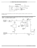
Page 12: ...re mounted on system supply side mounting on system return side is also acceptable practice BACK FLOW VALVE PIPING LEGEND Figure 4 2 Circulators Mounted on Supply System Boiler Used In Configuration with Chiller System See Special Conditions Below DRAIN PN 240012785 Rev C 11 15 2020 ...

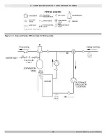
Page 13: ...gure 4 3 Bypass Piping With Automatic Mixing Valve BACK FLOW VALVE PIPING LEGEND 4 CONNECTING SUPPLY AND RETURN PIPING PURGE VALVE DRAIN VALVE ASME RELIEF VALVE BACK FLOW VALVE PN 240012785 Rev C 11 15 2020 ...

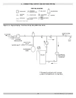
Page 14: ...PPLY AND RETURN PIPING Figure 4 4 Bypass Piping Fixed Low Temp Only With Zone Valve BACK FLOW VALVE PIPING LEGEND ASME RELIEF VALVE Manually adjust until proper system temperature is reached PN 240012785 Rev C 11 15 2020 ...

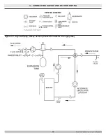
Page 15: ...TING SUPPLY AND RETURN PIPING Figure 4 5 Bypass Piping 4 Way Valve Option With Circulator On Supply side BACK FLOW VALVE PIPING LEGEND ASME RELIEF VALVE DRAIN VALVE FLOW CONTROL VALVE PN 240012785 Rev C 11 15 2020 ...

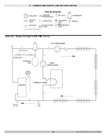
Page 16: ... 4 CONNECTING SUPPLY AND RETURN PIPING Figure 4 6 Single Zone System With DHW Priority BACK FLOW VALVE PIPING LEGEND ASME RELIEF VALVE Back Flow Valve DRAIN VALVE Purge Valve PN 240012785 Rev C 11 15 2020 ...

Page 17: ...ief Valve 1 DHW Pump 12 305 mm Recommended distance Do not exceed 12 Note Note Manufacturer requires all domestic hot water DHW installations use an anti scald valve Local codes may require additional equipment expansion tank relief valves etc Select and size equipment to suit installation and meet code requirements Hot Water Supply Tempered Note Refer to pump manufacturer literature for proper pu...

Page 18: ...r Infiltration Rate See Table 5 1 for space with boiler only Use equation for multiple appliances Do not use an air infiltration rate ACH greater than 0 60 Volume 21 ft3 ACH x Total Input Refer to National Fuel Gas Code for opening requirements between connected indoor spaces All Outdoor Air Provide permanent opening s communicating directly or by ducts with outdoors A Two Permanent Opening Method...

Page 19: ... operation the appliance being inspected Follow the lighting instructions Adjust thermostat so appliance will operate continuously 5 Test for spillage at the draft hood relief opening after 5 minutes of main burner operation Use the flame of a match or candle or smoke from a cigarette cigar or pipe 6 Minimum draft should be 02 w c 7 After it has been determined that each appliance remaining connec...

Page 20: ...od condition Installation must conform to requirements of the authority having jurisdiction or in absence of such requirements to The National Fuel Gas Code ANSI Z223 1 NFPA 54 7 4 Vent Pipe Connect draft hood to boiler using 2 screws provided onto flue collector Connect two safety circuit wires attached to vent damper harness to blocked vent switch See Figure 13 1 Fasten sections of vent pipe wit...

Page 21: ...accessible for servicing See Figure 8 2 page 22 4 Damper must be in the open position when appliance main burners are operating 5 Boiler is equipped with factory wired harness that plugs into vent damper 6 Slope pipe up from boiler to chimney not less than 1 4 per foot 7 Run pipe as directly as possible with as few elbows as possible 8 Do not connect to fireplace flue 9 End of vent pipe must be fl...

Page 22: ...22 Figure 8 2 Vent Damper Placement Figure 8 3 Vent Damper Position Indicator 8 VENT DAMPER INSTALLATION INSTRUCTIONS PN 240012785 Rev C 11 15 2020 ...

Page 23: ...supplier call the fire department INSTALL MANUAL VALVE WITHIN 6 FT 183 cm OF BOILER AND 5 FT 152 cm ABOVE THE FLOOR WHERE REQUIRED BY LOCAL CODES 3 8 cm Minimum Sediment Trap To Gas Control Inlet DANGER Fire Hazard Do not use matches candles open flames or other methods providing ignition source Failure to comply will result in death or serious injury WARNING Fire explosion asphyxiation and burn h...

Page 24: ... where it will be affected by drafts hot or cold pipes sunlight lighting fixtures televisions fireplace or chimney 5 Check thermostat operation by raising and lowering thermostat setting as required to start and stop burners 6 Instructions for final adjustment of thermostat are packaged with thermostat adjusting heating anticipator calibration etc 7 Thermostat s heat anticipator must be adjusted t...

Page 25: ...gure 11 1 3200 Plus Fuel Smart Hydrostat Control WARNING Modification substitution or elimination of factory equipped supplied or specified components may result in personal injury or loss of life PN 240012785 Rev C 11 15 2020 ...

Page 26: ...26 11 WIRING DIAGRAM Figure 11 2 3200 Plus Fuel Smart Hydrostat Control ladder PN 240012785 Rev C 11 15 2020 ...

Page 27: ...turn clockwise to OFF DO NOT FORCE 5 Call qualified service technician WARNING If you do not follow these instructions exactly a fire or explosion may result causing property damage personal injury or loss of life This appliance is equipped with an ignition device which automatically lights burner Do NOT try to light this burner by hand Before operating smell all around appliance area for gas Be s...

Page 28: ...these instructions could result in death or serious injury Ignition Control A Power remains off until boiler water temperature drops below high limit setting B Circulator continues to operate under this condition until thermostat is satisfied 3 In event the flow of combustion products through the boiler venting system becomes blocked A Blocked vent safety switch shuts main burner gas off B If boil...

Page 29: ... lamp in flue collector through draft relief opening or flue inspection cover With mirror positioned above burners flue gas passageways can be checked for soot or scale Follow this procedure to clean flue gas passageways 1 Remove burner tray from heat exchanger by disconnecting the gas supply by removing two 2 nuts Pull out the assembly see Figure 14 1 page 30 2 Remove top jacket panel 3 Remove fl...

Page 30: ...ar and free of combustible materials gasoline and other flammable vapors and liquids Free flow of combustion and ventilating air to boiler and boiler room shall not be restricted or blocked Inspect factory supplied and field sourced low water cutoffs annually or as recommended by low water cutoff manufacturer Flush float type low water cutoffs per manufacturer s instructions Contact a Qualified Se...

Page 31: ... column from specified pressure listed on boiler rating plate 7 Primary air adjustment is not necessary therefore air shutters are not furnished CHECK SAFETY CONTROL CIRCUIT Test ignition system safety shutoff device after placing boiler in operation Test ignition system safety shutoff device after placing boiler in operation Blocked vent switch and rollout switch can be tested by removing one of ...

Page 32: ... is 19 79 E 1 Input rating for sea level to 2 000 ft 610m above sea level United States over 2000 ft 610m above sea level Reduce input rate 4 for every 1000 ft 304m above sea level Canada 2000 ft 610m to 4500 1350m above sea level reduce input per table Over 4500 ft 1350m above sea level Contact Provincial authority having jurisdiction 2 Net AHRI Water Ratings shown based on piping and pickup allo...

Page 33: ... It will remain lit until the water temperature falls 10 The Fuel SmartHydroStat prevents burner operation while this LED is on See Differential explanation on page 6 of Hydrolevel Manual LWCO ACTIVE Indicates the low water cut off LWCO function of the Fuel Smart HydroStat is active When the control is installed with a Hydrolevel Electro Well this LED will be on at all times when the control is po...

Page 34: ...bent out of position restore to correct position If this LED is blinking and the burner is not firing Make sure the plug connection or jumper on boilers where vent damper plug is not used is secure Make sure the plug connection at the vent damper end is secure and oriented correctly Make sure damper motor turns Verify the damper end switch has closed DANGER Carbon Monoxide Hazard If the burner fir...

Page 35: ... 4 Verify pilot and main burner light off 1 Initiate call for heat Turn thermostat above room temperature Ignition sequence may be delayed by thermal purge up to 2 minutes 2 Watch pilot burner during ignition sequence Verify ignition spark stops within a few seconds after pilot is lit Verify Main burner lights within a few seconds of pilot lighting a Check pilot flame Verify it is blue steady and ...

Page 36: ...ed position 4 Return thermostat to desired position 5 Place vent damper in open position to permit burner operation by using HOLD DAMPER OPEN switch located on damper controller 6 Thermostat controls burner firing as before while damper remains open 7 DO NOT turn damper open manually motor damage will result 8 Set switch to AUTOMATIC OPERATION to close vent damper during burner off cycle 9 For fur...

Page 37: ...e jumper wire across orange and yellow wires in Molex plug see Figure 4 This will create bypass of the damper boiler should then ignite If boiler ignites Go to section B 4 Vent Damper Troubleshooting Guide If boiler does not ignite Problem is not the damper Go to Damper harness Molex on Aquastat Step C NOTE Prior to replacing the damper be sure the problem is not with wire connections between damp...

Page 38: ...for heat 1 Thermostat not calling for heat 2 Burned out heat anticipator 3 Loose or broken connections 4 Off On operating limit pressure control or low water cut off 5 Off On blocked vent switch or flame roll out 1 Turn thermostat up to call for heat 2 Replace thermostat 3 Tighten repair or replace connection 4 Turn operating limit pressure control or low water cutoff ON 5 Reset or replace switch ...

Page 39: ...39 NOTES PN 240012785 Rev C 11 15 2020 ...

Page 40: ...S OVERRIDE MUST NOT BE USED UNLESS AT LEAST ONE OF THE FOLLOWING CONDITIONS IS TRUE An external energy management system is installed that reduces the boiler water temperature as the heating load decreases This boiler is not used for any space heating This boiler is part of a modular or multiple boiler system having a total input of 300 000 BTU hr or greater This boiler is equipped with a tankless...

Reviews: