background image


Chapter 3: Installation Guide   

- 3 - 


Chapter 3: Installation Guide 

3.1 Installation   

First, please make sure that the switch installation environment meets the following 

requirements:   

1. The surface holding the switch must be secure enough to support weight of the 

switch and its mounting accessories;   

2. The power socket for power supply shall be within 1.5 m from the power socket 

of the switch;   

3.  Make  sure  there  is  sufficient  space  in  the  ventilation  outlet  of  the  switch  to 

ensure good ventilation and heat dissipation;   

4. Please install the power socket at accessible positions near the switch to make 

it easy for operation.   

NOTE: 

You must use a triplex receptacle with safe grounding and make sure earth wire of 

the power socket for power supply is reliably grounded. Make sure there is sufficient 

space for heat dissipation and ventilation for the switch. Do not place anything on 

the switch.   

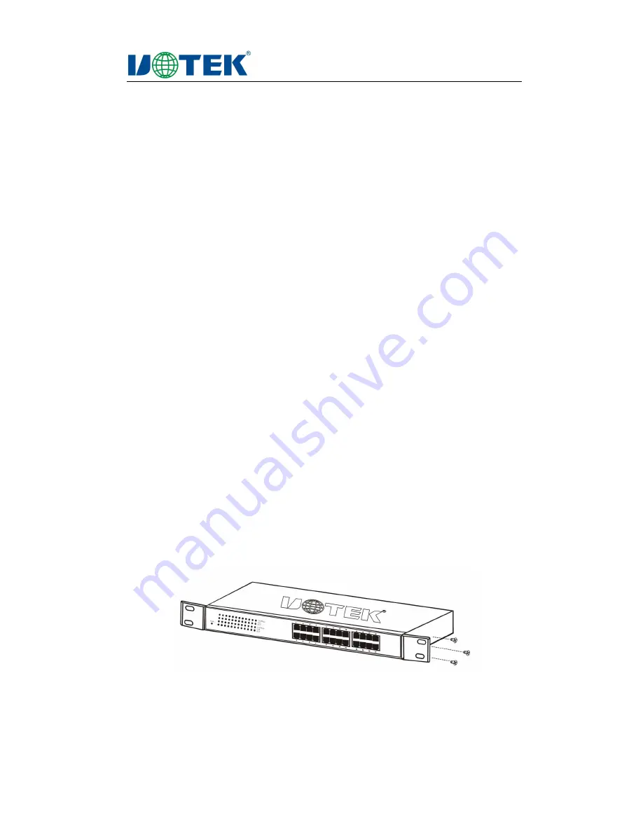
The  UT-6516U/UT-6524 switch  may  be  installed on  a  19-inch  standard  cabinet  in 

compliance with EIA (Electronic Industries Association). Prior to installation, turn off 

all connected devices. Mount the L-shaped supports onto both sides (one for each 

side) of front panel of the switch and fix it with screws. Then fix the switch on the 

switch support with screws.   


Fig.3-1: Mount L-shaped support onto the switch   


Summary of Contents for UT-6516U

Page 1: ...UT 6516U UT 6524 10 100M Unmanaged Ethernet Switch User Manual May 8 2013 Version V1 0 UTEK TECHNOLOGY SHENZHEN CO Ltd http www szutek cn ...

Page 2: ...e means for commodity circulation or other commercial and profitable purposes is a registered trademark of Shenzhen UTEK Technology Co Ltd All other trademarks or registered trademarks as mentioned in this document are properties of its corresponding owners Product specifications and information referred to in this Manual are for reference only and subject to updates without notice Unless otherwis...

Page 3: ...ing One UT 6516 UT 6524 switch One AC power cord One User s Manual One Warranty Card Two L shaped support to be fixed on the base and other accessories Notes In case of missing or damage of accessories please immediately contact the local distributor ...

Page 4: ... 1 2 General Description 1 Chapter2 Product Introduction 2 2 1 Product Overview 2 2 2 Performance Features 2 Chapter 3 Installation Guide 3 3 1 Installation 3 3 2 Initialization 4 Chapter 4 Product Design 5 4 1 Front Panel 5 4 2 Rear Panel 5 4 3 LED Lamps 5 4 ...

Page 5: ...ting the length of network cable and workload and to effectively reduce energy consumption The product supports a 19 inch standard base installation It is unmanaged and plug and play 1 1 Purpose This Manual is to help users get familiar with and correctly use the UT 6516U UT 6524 10 100M self adaptive Ethernet switch 1 2 General Description Chapter I Introduction to Manual Chapter II Product Intro...

Page 6: ...ble and workload and to effectively reduce energy consumption This series of switches features simple and flexible use easy installation excellent performance and high performance cost ratio making it the best choice for promoting server speed 2 2 Performance Features Follow the IEEE802 3 10BASE T Ethernet and IEEE802 3u 100BASE TX fast Ethernet standards The 16 24 10 100BASE T X ports supporting ...

Page 7: ...cket at accessible positions near the switch to make it easy for operation NOTE You must use a triplex receptacle with safe grounding and make sure earth wire of the power socket for power supply is reliably grounded Make sure there is sufficient space for heat dissipation and ventilation for the switch Do not place anything on the switch The UT 6516U UT 6524 switch may be installed on a 19 inch s...

Page 8: ...n on the power After startup the switch will automatically initialize and the LED lamps will appear as below Once the power is on all indicator lamps will light up for one second and then go out indicating the reset of the system The LED power indicator lamp will light up constantly NOTE If the initialization process is not consistent as described above please check whether the power supply is con...

Page 9: ... LED lamps and 16 24 ports 10 100 M Fig 4 1 Front Panel of UT 6516U Switch Fig 4 2 Front Panel of UT 6524 Switch 4 2 Rear Panel The rear panel of switch has a power socket AC100 240V 50 60Hz Fig 4 3 Rear Panel of UT 6516U UT 6524 4 3 LED Lamps The LED lamps include PWR 100 Mbps and Link Act These LED lamps enable easy monitoring and observing the working status of the switch Description of LED lam...

Page 10: ...nnected 100 Mpbs lamp speed indicator When one port is connected to a 100 Mbps device the corresponding LED lamp will light up in a constant green The LED lamp will not light up if one port is connected to a 10 Mbps device Link Act lamp linkage indicator When a port is connected to a network device the corresponding LED lamp will light up in a constant green After a port is connected the correspon...

Page 11: ...available independently as an uplink port 100Mbps HDX LED display Power indicator 100Mbps rate indicator speed indicator Link Act indicator 20Mbps FDX Transmission Mode Store and forward 200Mbps FDX MAC Address Learning Auto update Topological Structure Star Packet Filtering Rate 10Base T 14880pps port 100Base TX 148810pps port Physical Medium 10Base T Two UTP 100M category 3 4 5 Forwarding Rate 1...

Reviews: