UTC. All Rights Reserved.
3
P/N 0000000 – Rev. A – 06 Nov 12
D.
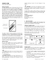
Slide the product body back onto the mounting plate.
Note:
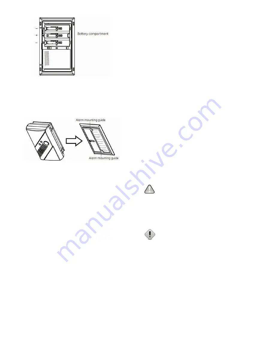
The mounting plate will not close if all three batteries are not
installed.
Sliding the alarm on the mounting plate
E.
Perform a sensor/RF test with the control panel. See “RF
communication test”.
When replacing the batteries, use one of the following approved
brands:
o
Duracell MN1500 or MX1500
o
Energizer E91
Note:
Use of a different battery may have a detrimental effect on the
alarm operation. Constant exposures to high or low humidity may
reduce battery life.
After installing or changing the batteries, reinstall your product. Test
your product by checking the green Power LED flashes once every 30
seconds and using the Test/Hush button to create an alarm condition.
6.
Adding to the Control Panel
Each product is programmed with a unique ID when manufactured.
The unique ID is enrolled into the control panel at the time of
installation, allowing the detector to communicate with that specific
control panel.
A.
Log in to the Settings app with an Installer code.
B.
In the Settings menu, tap Sensors & Zones > Add a Sensor/Zone.
C.
Place the product in Search mode and prepare it to be added to
the control panel (refer to the installation documentation for your
sensors). Available sensors meet the following requirements:
o
Defaulted.
o
Not currently paired with another control panel device.
o
Currently in Search mode.
D.
At the Locating Wireless Sensors screen, tap Next. A Done button
appears on the screen and the control panel searches for sensors
that are available to be added. As sensors are found, a grayed
icon appears for that sensor.
E.
Fault each found sensor to pair it to the control panel. The icon for
each sensor is undarkened as it is faulted and the control panel
beeps. The sensor is paired to the control panel.
F.
When all the sensors are found and paired, tap Stop. Any located
sensors that were not paired are released by the control panel
and can be added later. The Wireless Sensors Located screen
shows the number of wireless sensors found and paired.
G.
Tap Next. The Configure Wireless Sensors screen shows icons of
the sensors that were found and paired.
H.
Touch each sensor icon to configure the corresponding product.
The Add Sensor/Zone Modify screen appears.
I.
To change the product Icon (if multiple options are available), tap
the currently selected value.
J.
Tap Next. The Add Sensor/Zone Modify screen appears.
K.
To modify a text field on the control panel, tap the field, use the
onscreen keyboard to enter your changes, and tap Done to save
your changes.
L.
When all sensors are configured properly, tap Next in the
Configure Wireless Sensors screen.
M.
If all of the sensors have not been configured, the Modify screen
appears for each sensor to let you review its details. Change the
details as needed or tap Next to cycle through all the sensors. The
sensors are marked as configured.
7.
Testing the Product
This product may be tested during install or at anytime. It is
recommended the product be tested in place annually. This product is
sealed. The cover is not removable.
WARNING:
The control panel must be placed into sensor test
mode while conducting any tests. Placing the control panel into sensor
test mode for all testing helps to protect against false alarms and
unintentional central station reporting.
Due to the loudness of the alarm, we suggest that you place your
fingers over the sounder vent while testing your alarm.
Caution:
Continuous exposure to the high sound level of this
alarm over an extended period of time may cause hearing loss.
This product provides three test modes:
o
Normal CO Alarm Test.
Conducts an internal self test and tests
the sounder.
o
RF Communication Test.
Tests the communication path with
the control panel.
o
CO Alarm Functional Gas Test.
Tests the functional operation
of the CO sensing element.
Normal CO Alarm Test
A.
Wait at least 10 minutes after installation to test the CO Alarm.
B.
Make sure the green Power LED is flashing for normal
operation.
C.
Set the control panel to sensor test mode.
D.
Press and hold the Test/Hush button until the unit beeps once
(approximately 1 second), and then release the button. If the unit


