


© 2013 UTC RETAIL
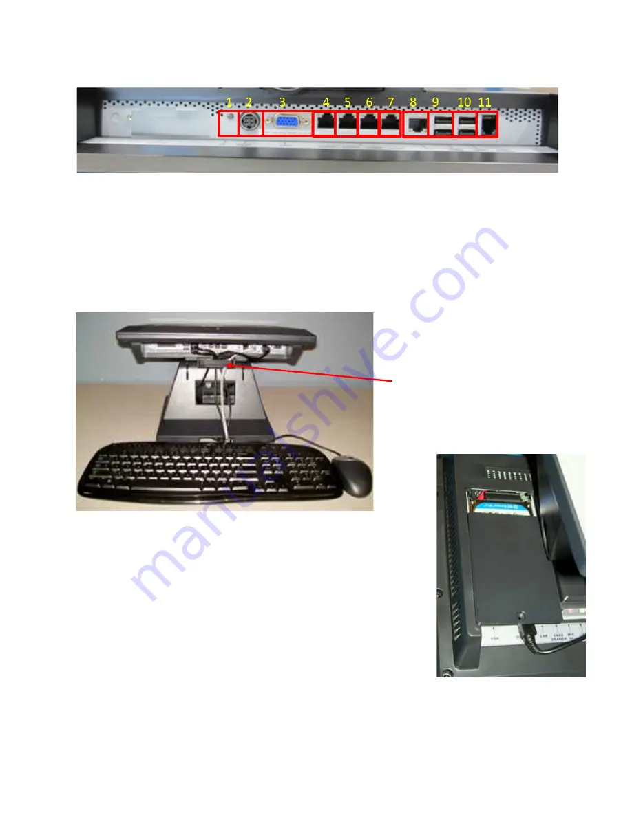
Input/Output Panel – Port Configuration
1.
Power switch
2.
DC in 19V
3.
VGA
4.
COM4
Cable Routing
For a neat installation, route the I/O panel cables through the cable tie down
Excess cable can be loomed under the 2170
Figure 3, 2170 I/O Panel and Cable Clamp Assembly
Hard Drive Removal
The 2170 POS System is equipped with one
drives.
To remove a hard drive, follow these steps
1. Shut off all power to the system;
from the AC outlet.
2. Remove the single screw on the rear panel and lift off the
hard drive access cover.
3. Disconnect the HDD cabling.
4. Replace hard drive.
5. Reconnect the cabling and install the door.
5
Port Configuration
Figure 2, 2170 POS I/O Panel
5.
COM3
6.
COM2
7.
COM1
8.
LAN
9.
USB3/USB4
10.
USB1/USB2
11.
Cash Drawer
For a neat installation, route the I/O panel cables through the cable tie down clamp assembly. See photo below.
2170 stand and hidden behind the system.
I/O Panel and Cable Clamp Assembly
POS System is equipped with one easily accessible hard
, follow these steps:
hut off all power to the system; unplug the power cord
Remove the single screw on the rear panel and lift off the
hard drive access cover.
Disconnect the HDD cabling.
Reconnect the cabling and install the door.
Secure cables using the cable tie
down clamp assembly.
Figure
under open door
11801016 Rev A
USB3/USB4
USB1/USB2
Cash Drawer
assembly. See photo below.
Secure cables using the cable tie
down clamp assembly.
Figure 4,2170 HDD seen
under open door


