background image


2 / 26 


P/N 466-5226-EMEA-

ML • REV B • ISS 09MAY16 

EN: Installation Sheet 

WARNING: 

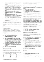
Important safety information. Read enclosed 

warnings and safety information. 

Description 

This installation sheet describes how to install RF-DC101 
Series 433 MHz Door/Window Sensor. The series include the 
following wireless sensors: 

• 

RF-DC101-K4 (white) 

• 

RF-DC101B-K4 (mahogany) 

You can install the sensor on doors, windows, and other 
objects that open and close. The sensor transmits signals to 
the control panel when a magnet mounted near the sensor is 
moved away from or closer to the sensor. The sensor is 
equipped with a wall and cover tamper for additional security. 

Figures 

Figure 1: Removing the battery pull tab 

(1)  Pull tab 

Figure 2: Removing the sensor cover 

(1)  Cover 
(2)  Press small screwdriver into slot and lift cover 
(3)  Cover screw mounting hole 

Figure 3: Inserting the battery 

Figure 4: Input selection jumper 

(1)  Input selection jumper 

Figure 5: External contact wiring 

(1)  Door/Window Sensor 
(2)  EOL resistor 
(3)  Contacts 

Figure 6: Mounting holes 

(T)  Mounting hole for T screw 
(L)  Mounting hole for L screw 

Figure 7: Sensor and magnet alignment 

(1)  Align marks 

Accessory packs 

White 

Mahogany 

10-pack spacer housing for 
sensor (RF-DC101SR-K4) 

10-pack spacer housing for sensor 
(RF-DC101BSR-K4) 

10-pack spacer housing for 
magnet (RF-DC101SM-K4) 

10-pack spacer housing for 
magnet (RF-DC101BSM-K4) 

Single large magnet (RF-
DC101BM-K4) 

Single large magnet (RF-
DC101BBM-K4) 

Installation guidelines 

Use the following installation guidelines: 

• 

Mount the sensor on the door frame. Mount the magnet on 
the door. If the sensor is used on double doors, mount the 
sensor on the least-used door and mount the magnet on 
the most-used door. 

• 

If possible, locate sensors within 60 m of the panel. 
A transmitter may have a range of 600 m or more out in 
the open, but the environment at the installation site can 
have a significant effect on transmitter range. Sometimes 
a change in sensor location can help overcome adverse 
wireless conditions. 

• 

When mounting, make sure the alignment arrow on the 
magnet points to the alignment mark on the sensor, and 
the gap between them is not bigger than 1 cm to ensure a 
pro

per “closed” condition on metal surfaces. See Figure 7. 

• 

Place sensors at least 12 cm above the floor to avoid 
damaging them. 

• 

Avoid mounting sensors in areas where they will be 
exposed to moisture or where the sensor operating 
temperature range of 

−10 to 55°C will be exceeded. 

• 

Mount directly to a stud if possible. If a stud is not 
available, use wall anchors. 

• 

Avoid mounting the sensor in areas with a large quantity of 
metal or electrical wiring.  

• 

End-of-line (EOL) resistors must always be connected to 
the external contact terminals if the external contact is 
being used. See 

“External contact wiring” on page 3 for 

proper wiring details. 

• 

Mount sensors with screws, not double-sided tape. 

Caution:


You must be free of static electricity when handling 

electronic components. Touch a grounded bare metal surface 
before touching a circuit board or wear a grounded wrist strap. 

Programming 

The following steps describe general guidelines for 
programming (learning) the sensor in to panel memory. Refer 
to the specific panel and/or receiver’s documentation for 
complete programming details. 

1.  Set the panel to program mode. 

2.  At the LEARN SENSORS menu, select the appropriate 

sensor group and sensor number assignments. 

3.  When prompted by the panel to trip the sensor for 

learning, remove the battery pull tab (Figure 1) or remove 
the sensor cover (Figure 2) and if required insert the 
battery into the holder, observing correct polarity 
(Figure 3). 

4.  The system should acknowledge learning the sensor by 

touchpad display and/or audio (depending on the panel). 

5.  Exit program mode. 

Input selection 

Only one internal reed switch can be used at any given time.  

Position the input selection jumper to select internal reed 
switch 1, internal reed switch 2, or external contact only 
(Figure 4, item 1). 


Reed 1 


Reed 2 


External only 

Summary of Contents for interlogix RF-DC101 Series

Page 1: ...mericas Corporation Inc 1 26 P N 466 5226 EMEA ML REV B ISS 09MAY16 RF DC101 Series 433 MHz Door Window Sensor Installation Sheet EN DE ES FR IT NL PL PT SV 1 2 3 4 5 6 7 1 1 2 3 Z X Y 1 2 4 7 kΩ 2 4 7 kΩ 1 3 T L 1 cm 1 cm 1 1 ...

Page 2: ...t on transmitter range Sometimes a change in sensor location can help overcome adverse wireless conditions When mounting make sure the alignment arrow on the magnet points to the alignment mark on the sensor and the gap between them is not bigger than 1 cm to ensure a proper closed condition on metal surfaces See Figure 7 Place sensors at least 12 cm above the floor to avoid damaging them Avoid mo...

Page 3: ...t from its base 6 Line up the arrow on the magnet with the small notch on the side of the sensor Figure 7 depending on the internal reed switch being used Figure 4 7 Mount the magnet base with the 3 5 x 16 mm pan head screws no more than 1 cm away from the sensor base Replace the magnet cover 8 Attach the sensor cover to the sensor base and secure with the 2 9 x 6 5mm pan head screw Figure 2 Batte...

Page 4: ...er RF DC101 Serie beschrieben Die Serie umfasst die folgenden Funksensoren RF DC101 K4 weiß RF DC101B K4 mahagoni Sie können den Sensor auf Türen Fenstern und sonstigen Objekten anbringen die sich öffnen und schließen lassen Der Sensor übermittelt Signale an die Einbruchmeldezentrale wenn ein in der Nähe des Sensors montierter Magnet vom Sensor weg oder näher zum Sensor hin bewegt wird Der Sensor ...

Page 5: ...endet werden Positionieren Sie die Eingangsauswahl Steckbrücke auf den internen Reed Schalter 1 internen Reed Schalter 2 oder nur externen Kontakt Abbildung 4 Element 1 Reed 1 Reed 2 Nur extern Hinweis Während der Positionierung der Eingangsauswahl Steckbrücke sollte das Gerät ausgeschaltet sein Externer Kontakt Beschaltung Verwenden Sie die folgenden Spezifikationen für den externen Kontakt Maxim...

Page 6: ...bstände Montage auf nicht ferromagnetischen Material Annäherungs Abstand X Schalter geschlossen 7 mm Entfernungs Abstand X Schalter geöffnet 13 mm Annäherungs Abstand Z Schalter geschlossen 30 mm Entfernungs Abstand Z Schalter geöffnet 41 mm Annäherungs Abstand Y Schalter geschlossen 20 mm Entfernungs Abstand Y Schalter geöffnet 30 mm Toleranzen für alle Abstände 10 Für X Y Z Abstands Erklärung si...

Page 7: ...as para el sensor RF DC101BSR K4 Paquete de 10 carcasas espaciadoras para el imán RF DC101SM K4 Paquete de 10 carcasas espaciadoras para el imán RF DC101BSM K4 Imán grande único RF DC101BM K4 Imán grande único RF DC101BBM K4 Instrucciones para la instalación Siga estas instrucciones de instalación Coloque el sensor en el marco de la puerta y el imán en la puerta Si el sensor se va a utilizar en pu...

Page 8: ...orrecta supervisión Esto ofrece las siguientes lecturas en el caso de una configuración normalmente cerrada Apertura cierre no se usa el tamper o los contactos externos 1 R 4 7 kΩ todos los dispositivos están cerrados un EOL 2 R 9 4 kΩ Alarma ambos EOL Verificación de la comunicación por RF Antes de montar el sensor verifique que la ubicación del sensor deseada proporciona una buena comunicación p...

Page 9: ...nados con los 433 productos y software ya estén basados en garantía contrato o agravio En ningún caso UTC será responsable ante usted y otras personas de las cantidades que excedan la cantidad realmente recibida por UTC para los 433 productos o software Información normativa Fabricante COMERCILIZADO POR UTC Fire Security Americas Corporation Inc 3211 Progress Drive Lincolnton NC 28092 EE UU REPRES...

Page 10: ... de contact externes Voir Câblage du contact externe ci dessous pour plus de détails sur le câblage Installez les capteurs avec des vis N utilisez pas de bande adhésive double face Attention vous devez vous décharger de toute électricité statique avant de manipuler tout composant électronique Pour ce faire touchez une surface métallique avant de toucher une carte de circuits imprimés ou portez un ...

Page 11: ...z les piles recommandées voir Caractéristiques techniques ci dessous ou contactez d assistance technique pour plus d informations Pour remplacer les piles 1 Retirez le cache du capteur figure 2 2 Retirez la pile et mettez la au rebut conformément aux réglementations locales 3 Insérez la nouvelle pile en respectant la polarité figure 3 4 Testez le capteur avec la centrale Reportez vous à la section...

Page 12: ...ioni importanti sulla sicurezza Leggere le avvertenze e le informazioni sulla sicurezza allegate Descrizione Queste istruzioni per l installazione illustrano come installare il sensore porta finestra serie RF DC101 433 MHz Questa serie include i seguenti sensori wireless RF DC101 K4 bianco RF DC101B K4 mogano Il sensore può essere installato su porte finestre e su molti altri oggetti che si aprono...

Page 13: ...terno 1 l interruttore a lamelle interno 2 o solo il contatto esterno figura 4 voce 1 Reed 1 Reed 2 Solo esterno Nota Il dispositivo deve essere spento mentre viene posizionato il ponticello selezione ingresso Cablaggio contatto esterno Utilizzare le seguenti specifiche per il contatto esterno Lunghezza massima del cavo 30 m Intrecciato Ø 0 5 1 0 mm 24 18 AWG Contatti esterni ermetici reed sigilla...

Page 14: ...declina tutte le dichiarazioni e garanzie esplicite o implicite legali o di altra natura che includano a titolo esemplificativo qualsiasi garanzia di commerciabilità o idoneità per uno scopo specifico in relazione ai prodotti 433 e al relativo software UTC non garantisce che i prodotti e il software 433 i non vengano violati manomessi o elusi oppure che ii evitino o forniscano avvisi adeguati o pr...

Page 15: ...ik kan de omgeving van de installatie een aanzienlijke invloed hebben op het bereik van de zender Een wijziging in de detectorlocatie kan u helpen om nadelige storingen van draadloze componenten op te lossen Bij montage zorg ervoor dat de uitlijning pijl op de magneet wijst naar de uitlijningsmarkering op de sensor en de ruimte tussen beide niet groter is dan 1 cm om een juist gesloten status te g...

Page 16: ...palen raadpleeg de specifieke documentatie voor paneel ontvanger 5 Sluit de testmodus voor de detector af Montage Monteer de detector als volgt 1 Monteer de voet van de detector met behulp van twee schroeven van 3 5 x 25 mm op de T en L montagegaten afbeelding 6 2 Plaats zowel de T als de L schroef en draai ze tot halverwege aan 3 Breng eerst de L schroef in de goede stand en draai deze vervolgens...

Page 17: ...Progress Drive Lincolnton NC 28092 VS GEAUTORISEERDE EU VERTEGENWOORDIGER UTC Fire Security B V Kelvinstraat 7 6003 DH Weert Nederland Certificatie EN 50131 EN 50131 2 6 Grade 2 Omgevingsklasse II Getest en gecertificeerd door Telefication Richtlijnen van de Europese Unie UTC Fire Security verklaart hierbij dat dit apparaat voldoet aan de van toepassing zijnde vereisten en bepalingen van een of me...

Page 18: ...nki elektrostatyczne z ciała Przed dotknięciem płytki drukowanej dotknąć uziemionej niepomalowanej metalowej powierzchni lub założyć opaskę uziemiającą na nadgarstek Programowanie Poniższe kroki zawierają ogólne zalecenia dotyczące programowania uczenia się czujnika w pamięci centrali Szczegółowe informacje na temat programowania zawiera dokumentacja danej centrali i lub czujnika 1 Ustawić central...

Page 19: ...iowy RF DC101B K4 Częstotliwość 433 MHz Maksymalna moc wyjściowa 10 mW Kompatybilność Panele sterowania odbiorniki Interlogix 433 MHz zgodne z protokołem 80Plus Typ baterii Litowa 3 0 V 1300 mAh Zalecane baterie Duracell DL123A Energizer EL123AP Szacowana żywotność baterii 5 lat przy sygnałach nadzoru emitowanych co 15 minut i 4 aktywacjach na godzinę Odstęp czasowy nadzoru mniej niż 20 minut Pobó...

Page 20: ... lingueta de puxar da pilha 1 Lingueta de puxar Figura 2 Remoção da tampa de sensor 1 Tampa 2 Pressione uma chave de fendas pequena para dentro da ranhura e levante a tampa 3 Orifício de montagem do parafuso da tampa Figura 3 Inserção da pilha Figura 4 Jumper de selecção de entrada 1 Jumper de selecção de entrada Figura 5 Cablagem de contacto externo 1 Sensor de porta janela 2 Resistência EOL 3 Co...

Page 21: ...terno em simultâneo Pode ligar até cinco contactos externos em série Pode ligar os blocos de terminais nos sensores com cabos de um contacto externo O contacto inclui indicação de alarme e de tamper O contacto externo está ligado com duas resistências de fim de linha EOL uma em série e outra passando o contacto externo Figura 5 item 2 As resistências EOL têm de ser instaladas no dispositivo de det...

Page 22: ...ão os resultantes de lucros cessantes perda de dados ou outra perda de vantagem económica decorrentes da utilização incapacidade de utilização ou dos resultados da utilização dos produtos e software 433 ou outros de qualquer forma ligados a estes seja com base na garantia contrato ou delito A UTC não é responsável em caso algum em relação a si ou terceiros por qualquer montante em excesso do monta...

Page 23: ...ingar Ändmotstånd EOL måste alltid anslutas till de externa kontaktanslutningarna om den externa kontakten används Se Externa kontaktledningar nedan för korrekt ledningsinformation Montera sensorer med skruvar inte dubbelhäftande tejp Varning Du måste vara fri från statisk elektricitet när du hanterar elektroniska komponenter Rör en jordad ren metallyta innan du rör kretskortet eller bär ett jorda...

Page 24: ...nikation ovan Specifikationer Modellnummer Vit RF DC101 K4 Mahogny RF DC101B K4 Frekvens 433 MHz Maximal uteffekt 10 mW Kompatibilitet Interlogix 433 MHz centralapparater mottagare med 80Plus protokoll Batterityp 3 0 V 1 300 mAh litium Rekommenderade batterier Duracell DL123A Energizer EL123AP Förväntad batterilivslängd 5 år med övervakningssignaler var 15 minut och 4 aktiveringar per timme Överva...

Page 25: ...rektiv UTC Fire Security intygar härmed att denna enhet uppfyller krav och bestämmelser enligt ett eller flera av direktiven 1999 5 EC 2014 30 EU och 2014 35 EU För ytterligare information se www utcfireandsecurity com eller www interlogix com 2002 96 EG WEEE direktivet Produkter som är markerade med denna symbol får inom Europeiska unionen ej kasseras som osorterat hushållsavfall Lämna in produkt...

Page 26: ...26 26 P N 466 5226 EMEA ML REV B ISS 09MAY16 ...

Reviews: