background image


ii 

Concord 4 Installation Manual 

Troubleshooting    106


Appendix A

 System planning sheets   117


Customer  information    118


Wireless devices   118


Hardware  devices   119


Zone  and sensor  assignments    121


System  settings index  and record   124


Appendix B

 Reference tables   129


Sensor group  characteristics   130


Sensor text    134


System  event  triggers   136


Sensor group  event  triggers   137


Sensor number  event  triggers   138


System  feature  event  triggers   141


Response  characteristics   143


Response  numbers    143


Specifications   145


Summary of Contents for interlogix Concord 4

Page 1: ...Concord 4 Installation Manual P N 466 2182 REV J NOV12 ...

Page 2: ...nts of this document For the latest documentation contact your local supplier or visit us online at www utcfireandsecurity com This publication may contain examples of screen captures and reports used in daily operations Examples may include fictitious names of individuals and companies Any similarity to names and addresses of actual businesses or persons is entirely coincidental Trademarks and pa...

Page 3: ...0 modules 22 Phones 28 Power 30 Chapter 3 Programming 33 Overview 34 Quick programming mode 36 Tier 1 programming menus 37 Tier 2 programming menus 40 Security menu 45 Phones menu 50 Phone options menu 54 Timers menu 57 Light control menu 59 Touchpad options menu 60 Reporting menu 61 Siren options menu 66 Sensors menu 67 Audio verification menu 71 Accessory modules menu 73 Onboard options menu 78 ...

Page 4: ...ces 119 Zone and sensor assignments 121 System settings index and record 124 Appendix B Reference tables 129 Sensor group characteristics 130 Sensor text 134 System event triggers 136 Sensor group event triggers 137 Sensor number event triggers 138 System feature event triggers 141 Response characteristics 143 Response numbers 143 Specifications 145 ...

Page 5: ... included for you to record hardware layout and software programming settings Use this manual for the following panels 600 1021 95R Concord 4 RF 600 1022 95R Concord Express V4 600 1040 Concord Commercial V4 600 1042 Concord Hybrid When necessary this manual refers you to other documentation with compatible peripherals The Concord 4 User Manual P N 466 2183 contains user worksheets that you should...

Page 6: ......

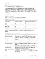
Page 7: ...ion Manual 1 Chapter 1 Introduction Summary This chapter provides information to help you plan your Concord 4 panel and system installation Content Planning the installation 2 Standard panel 2 SuperBus 2000 bus devices 3 ...

Page 8: ...lities Power Input for an AC step down plug in style transformer Auxiliary power output Output that supplies 9 to 14 VDC with up to 1 amp for bus devices and hardwired detectors such as smoke and motion detectors Bus A and B Input and output that provides communication between bus devices and the panel Siren driver Output that can drive an 8 ohm load and provides intrusion and fire alarm sounds fo...

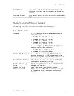
Page 9: ...00 touchpad Use the following touchpads for installer quick programming system operation and user programming SuperBus 2000 fixed display touchpad SuperBus 2000 FTP 1000 touchpad SuperBus 2000 RF transceiver Use the transceiver to receive signals from sensors and touchpad that may be on the fringe of panel reception The transceiver is compatible with all 319 5 MHz crystal and SAW learn mode wirele...

Page 10: ...2000 four relay output module HOM Provides four form C relay outputs that can be set up to activate other signaling devices based on system events Interrogator 200 audio verification module Allows central station operators to listen in and talk to occupants on the premises to verify the emergency when an alarm report is received SuperBus 2000 energy saver module ESM Provides a money saving and con...

Page 11: ...Concord 4 Installation Manual 5 Chapter 2 Installation Summary This chapter provides information on locating and installing the panel and system components Content Error Bookmark not defined ...

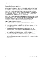
Page 12: ...d the cable jacket must be separated from all other conductors by a minimum of 0 25 in or by a nonconductive barrier Use the following installation guidelines Centrally locate the panel with relation to detection devices whenever possible to help reduce wire run lengths and labor Locate the panel where the temperature will not exceed 120 F 49 C or fall below 32 F 0 C Avoid running wires parallel w...

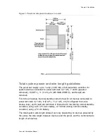
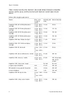
Page 13: ...NE 8 and SnapCard terminals For 24 hour backup the total standby current draw for all devices connected to panel terminals 4 12V 9 OUT1 11 12V 24 if configured for 2 wire smoke loop and SnapCard terminals is limited to 90 mA during normal standby condition using a 4 5 or 5 0 Ah battery or 190 mA during normal standby condition using a 7 0 Ah battery The total system wire length allowed can vary de...

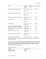
Page 14: ...umeric touchpad 22 ga 300 ft 18 ga 750 ft 30 mA 165 mA SuperBus 2000 fixed display touchpad 22 ga 300 ft 18 ga 700 ft 11 mA 65 mA SuperBus 2000 FTP 1000 fixed display touchpad 22 ga 300 ft 18 ga 700 ft 12 mA 75 mA SuperBus 2000 RF transceiver 22 ga 1 000 ft 18 ga 2 500 ft 45 mA 55 mA SuperBus 2000 phone interface voice module 22 ga 40 ft 18 ga 120 ft 25 mA 600 mA SuperBus 2000 voice only module 22...

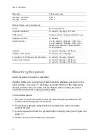
Page 15: ...e smoke detectors system sensor 2400 2400TH 22 ga 330 ft 18 ga 330 ft 120 µA 80 mA Hardwired interior siren 13 949 22 ga 750 ft 18 ga 1 500 ft 0 mA 85 mA Piezo dynamic exterior siren 13 950 22 ga 750 ft 18 ga 1 500 ft 0 mA 150 mA Speaker siren 60 528 or 13 060 18 ga 100 ft 0 mA 500 mA Maximum current draw for the SnapCards does not include the load which may be applied to their auxiliary DC supply...

Page 16: ...rophone 4 conductor 22 gauge shielded 2 wire smoke detectors 2 conductor 22 gauge 330 ft max 2 conductor 18 gauge 830 ft max Mounting the panel Mount the panel to the wall or wall studs Caution Make sure you are free of static electricity whenever you work on the panel with the cover open To discharge any static first touch the metal panel chassis and then stay in contact with the chassis when tou...

Page 17: ...uchpad header Mounting hole Antennas Mounting hole Snapcard connector Processor Terminal strip Mounting hole Grounding the panel For maximum protection from lightning strikes and transients connect the enclosure to earth ground as shown in Figure 3 below Use 16 gauge solid copper wire from an earth grounded cold water pipe clamp to the enclosure Figure 3 Grounding the panel Grounding wire Water pi...

Page 18: ...12 Concord 4 Installation Manual Antenna shrouds Install a plastic antenna shroud included with panel over each antenna and snap them into the holes on the top of the enclosure skip this step for hybrid and commercial systems ...

Page 19: ...Figure 4 below to install an optional SnapCard Install the SnapCard onto the panel SnapCard header and secure it in place with two screws included with the SnapCard To connect all necessary input output wiring refer to the SnapCard documentation Figure 4 Installing a SnapCard Mounting hole Snapcard connector Snapcard Mounting hole ...

Page 20: ... 26 27 28 16 5 VAC GND 12V A B SPKR SPKR OUT1 OUT2 12V MIC GND ZONE1 ZONE2 GND ZONE3 ZONE4 GND ZONE5 ZONE6 GND ZONE7 ZONE8 GRN BRN GRY RED Zones The panel comes with factory programmed onboard hardwired zones Install 2 kohm end of line EOL resistors on all unused factory programmed onboard hardwired zones If you don t want to install EOL resistors delete any unused zones from memory Zone inputs 1 ...

Reviews: