background image

11

Relay option

The reader has an open collector output available (violet wire) that can be activated by several events.
To set the event, do the following:

Table 3

 describes the options.

2. Press 

Menu 

to toggle between the options. Press 

Enter 

to exit and save the displayed option.

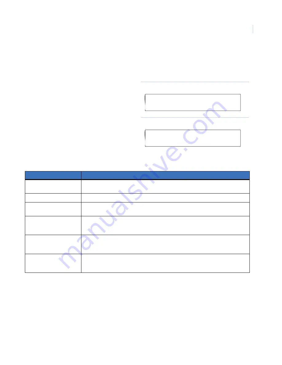
1. From the display in 

Figure 27

enter 

8

 and 

press 

Enter

 to access option 8.

The default display shows 

Door Relay


(

Figure 28

).

Figure 27. Smart reader menu display

Figure 28. Door relay display

Table 4.

Protocol options

Protocol

Description

Door relay

Activates (active low) when a valid card is presented to a door and the event flag and 

output controller have been set properly. Only available online.

Tamper O/P

Activates (active low) when a RAS tamper is present. Available online and offline.

Mag stripe data present

Activates (active low) when a magnetic stripe (smart card) is presented to a Track 2 

magnetic stripe interface. Only available offline.

Credit relay pulsed

Activates (active low) as pulse when a credit transaction is successfully completed. 

Duration is 10 msec. to 2.55 seconds, set in relay time factor. The reader has to be set up 

as a credit activated device.

Credit relay timed

Activates (active low) for a set duration when a credit transaction is successfully 

completed. Duration is 1 second to 65535 seconds multiplied by the relay time factor. 

The reader has to be set up as a credit activated device.

Credit relay latched

Activates when a smart card with valid data is badged and the credit transaction is 

successfully completed. When the text card is presented, the output will deactivate. 

The reader has to be set up as a credit device.

Smart Reader AL-1191/AL-1193
0-Exit, Menu:

Door Relay
*-Change, #-Exit

Summary of Contents for interlogix AL-1191

Page 1: ...Smart Card Reader Programming Manual ...

Page 2: ...nditions of this Agreement UTC Fire Security grants You a nonexclusive license to use the accompanying software including any upgrades modified versions updates additions and copies of the software furnished to You during the term of the Agreement Software and all associated media printed materials and electronic documentation accompanying the Software Documentation but only in the country where a...

Page 3: ...ability UTC Fire Security s sole obligation or liability under this agreement is the repair or replacement of nonconforming software and or defective media according to the limited warranty above In no event will UTC Fire Security be liable for any damages whether consequential incidental or indirect nor for any loss of data loss of profits or lost savings arising out of use of or inability to use...

Page 4: ...al device pursuant to part 15 of the FCC Rules These limits are designed to provide reasonable protection against harmful interference when the equipment is operated in a residential environment This equipment generates uses and can radiate radio frequency energy and if not installed and used in accordance with the instruction manual may cause harmful interference to radio communications You are c...

Page 5: ...nes 3 System databus programming 4 Local DGP databus programming 5 LED online settings 7 Night light 9 Protocol options 10 Relay option 11 Configuration cards 12 Reader address 13 Last card badged 14 Credits and relay time 15 Last card badged credit check 16 Alliance management software programming 17 Contacting technical support 18 Online publication library 18 ...

Page 6: ...Smart Card Reader Programming Manual vi ...

Page 7: ...publication library Note A qualified service person complying with all applicable codes should perform all required hardware installation Conventions used in this document The following conventions are used in this document Safety terms and symbols These terms may appear in this manual Bold Menu items and buttons Italic Emphasis of an instruction or point special terms File names path names window...

Page 8: ...t Card Programmer AL 1623 with the Alliance management software see Alliance management software programming on page 17 To program the reader using either the control panel or DGP programming menu you must connect the readers to the databus and program them one at a time before you install them at their permanent locations The default address is always 16 you must change the address for each reade...

Page 9: ...ress Clear to exit the menu Programming guidelines To program the menu options use the following guidelines To program a value such as a number or amount enter the valueand press Enter The information will be added and the display will show the new setting Press Enter to accept the display You can enter time settings in seconds or minutes Press Menu to toggle between seconds and minutes in the dis...

Page 10: ...ecommend that you always choose the advanced menu option Figure 4 Simple advanced menu display 4 Enter 3 and press Enter to access the RAS database Enter 16 address of the RAS to poll and press Enter Press Clear to exit this menu Access Option 28 remote devices Enter 28 and press Enter Figure 5 Figure 5 Installer programming display 5 Select RAS programming Enter 2 and press Enter Figure 6 Figure ...

Page 11: ...tion will limit access to a number of options in installer programming We recommend that you always choose the advanced menu option Figure 11 Simple advanced menu display 4 Access Option 28 remote devices Enter 28 and press Enter Figure 12 Figure 12 Installer programming display 5 Select DGP programming Enter 1 and press Enter Figure 13 Figure 13 Remote devices display 6 Enter the address of the D...

Page 12: ...ess DGP options Figure 16 Figure 16 DGP option display 9 Press Enter to scroll through the options until the display shows Figure 17 Enter the reader address 16 is the default and press Enter Figure 17 RAS polling display 1 DGP Options Menu No RAS are being polled Poll RAS ...

Page 13: ...played option 1 From the display in Figure 18 enter 1 and press Enter to access option 1 Figure 18 Smart reader menu display 2 To set the blue LED enter 1 and press Enter Figure 19 The default display shows Door Open Only Figure 20 Figure 19 LED display Figure 20 Door open only display Table 1 Blue LED options Option Blue LED is off Blue LED is on Blue LED flashes Door open only Door closed Door o...

Page 14: ...on 4 To set the red LED enter 2 and press Enter Figure 21 The default display shows Area Secure Figure 22 Figure 21 LED display Figure 22 Area secure display Table 2 Red LED options Option Red LED is off Red LED is on Red LED flashes Area secure Disarmed Armed Area secure plus door open Disarmed Armed Door open 1 Blue LED 2 Red LED No Area Secure Change Exit ...

Page 15: ...lowing 2 Press Menu to toggle between the enabled and disabled options Press Enter to exit the menu and save the displayed option 1 From the display in Figure 23 enter 4 and press Enter to access option 4 The default display shows Night Light Enabled Figure 24 Figure 23 Smart reader menu display Figure 24 Night light enabled display Smart Reader AL 1191 AL 1193 0 Exit Menu Night Light Enabled Chan...

Page 16: ...rt reader menu display Figure 26 Wiegand display Table 3 Protocol options Protocol Description Wiegand All data is transmitted both online and offline in the Wiegand protocol The information on the card decides which format can be used i e Aritech Tecom ASP or Standard 26 bit format Mag stripe All data is transmitted both online and offline in the Track 2 Magnetic Stripe format A card present sign...

Page 17: ...ble online and offline Mag stripe data present Activates active low when a magnetic stripe smart card is presented to a Track 2 magnetic stripe interface Only available offline Credit relay pulsed Activates active low as pulse when a credit transaction is successfully completed Duration is 10 msec to 2 55 seconds set in relay time factor The reader has to be set up as a credit activated device Cre...

Page 18: ...d save the displayed option Note To enable the option card again change this option to enabled default the reader or set this option in a configuration card if this option has not been used already After disabling this option a configuration card can only be used once 1 From the display in Figure 29 enter 9 and press Enter to access option 9 The default display shows Option Card Enabled Figure 30 ...

Page 19: ...ing on page 4 to poll the new RAS address and stop polling RAS address 16 1 From the display in Figure 31 enter 12 and press Enter to access option 12 Figure 31 Smart card reader display 2 Enter the new address number and press Enter Figure 32 Figure 32 Current RAS address display 3 Press Menu to change the address Figure 33 Figure 33 Change address display 4 Press Enter to return to the main menu...

Page 20: ...details of the last card badged do the following 1 From the display in Figure 36 enter 13 and press Enter to access option 13 Figure 36 Smart card reader display 2 The display Figure 37 shows FC System code five digits maximum ID Card number seven digits maximum Press Enter to exit the menu Figure 37 Card display Smart Reader AL 1191 AL 1193 0 Exit Menu FC XXXXX ID YYYYYYY Exit ...

Page 21: ...el required and press Enter Figure 41 Figure 41 Access level display 5 Enter the location number and press Enter Figure 42 Figure 42 Location number display 6 Enter the relay time factor and press Enter Figure 43 Figure 43 Relay time factor display 7 If no credit relay is set in option 8 seeRelay option on page 11 a warning appears Figure 44 Press Enter to exit the menu Figure 44 Warning display S...

Page 22: ...ress Menu to view the access level Figure 46 Card locations display 3 The display Figure 47 shows the access level This number must be equal to or greater than the reader access level Press Menu to view the account numbers and credits Figure 47 Card access level display 4 The display Figure 48 shows the account number and credits for account 1 Repeat for accounts 2 3 and 4 Press Enter to exit the ...

Page 23: ...ol g Select Valid Card Beep to enable the beeper option h Select Watchdog to enable the watchdog option i Select the required protocol from Output Options j Select Read Option Card to enable the option cards k Select the required protocol in Egress Control l Set up the credit usage and relay timing Set the token value in Reader Token Value Select the reader s credit account to subtract from in Rea...

Page 24: ... available to all of our customers on our website To access our publication library go to our website at the following location http www utcfireandsecurity com In the Customer Support menu select the Resource Library link After you register and log on you may search through our online library for the documentation you need 1 Table 5 Sales and support contact information Sales Technical support Pho...

Reviews: