Forney Corporation
UNIFLAME User’s Manual
Publication 372000-48 Rev H
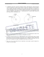
3. Consideration must be given to burner secondary air rotation, some burners have clockwise (CW) air
rotation and others have counter clockwise (CCW) air rotation. If combustion air enters the furnace
with a rotational movement of sufficient velocity to deflect the igniter flame in the direction of
rotation, position the detector 10 to 30 degrees downstream of the igniter as shown in Figure 5 and
close to the periphery of the burner throat. On opposed fired burners, avoid sighting main flame
detector with igniter on opposite wall, i.e., 3 o’clock igniter with 9 o’clock main flame detector and
mirror-image burner on the opposite wall.
Figure 5 – Air Rotation
4. A minimum sight tube diameter of 2 inches is desired for optimal view of a flame through a 4-foot
windbox. Use no more than one foot of one-inch diameter sight pipe. Increase the sight pipe diameter
one inch for every additional 2 feet of sight pipe length used to avoid restricting the detector’s field of
view.
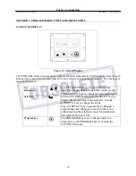
5. For ease of use, the detector should be installed on a sight pipe, so the LED display can easily be read.
Please note that the operation of the LED display is independent of position.
6. The detector lens must be kept free of contaminants (oil, ash, soot, dirt) and the detector housing
temperature must not exceed its maximum rating of 150°F (65°C). Minimum cooling air requirements
for each detector are listed on the project submittal drawings. If cooling air is not available from the
plant, Forney’s dual blower assembly with automatic failover logic can be offered.
7. Please note, the real time internal detector temperature and maximum recorded temperature is
available via the LED display.
7


