background image

2

June 2011

06-237172-001 Rev AA

CONTROL CROSS REFERENCE

INSTALLATION GUIDELINES

MOUNTING AND WIRING

The 35-63J is not position sensitive and can be mounted verti-
cally or horizontally. The case may be mounted on any surface 
with #6 sheet metal screws.

HIGH VOLTAGE TERMINAL CONNECTION

The Fenwal 35-63J uses a Rajah (spark plug) type HV connec-
tion which is common to most controls. If the control being 
replaced does not utilize a Rajah connection, the HV spark 
cable will need to be replaced or re-terminated using a Rajah 
style female mating connector.

Manufacturer/ Model Number

Johnson Controls

Fenwal Replacement

G770KGA-1,3

35-63J101-011

G770KHA-2

35-63J101-011

G770LGA-1,2

35-63J103-013

G770LGC-1,2,3,4,10

35-63J103-013

G770LHA-1,2

35-63J103-013

G770LHC-1

35-63J103-013

G770MGA-1,2,5

35-63J101-015

G770MHA-2

35-63J101-015

G770MGC-1,3

35-63J101-415

G770MHC-1

35-63J101-415

G770NGA-1

35-63J103-017

G770NGC-4,5,6,7

35-63J103-017

G770NHA-1

35-63J103-017

G770NHC-1

35-63J103-017

G770RHA-2

35-63J103-017

G77RJA-1

35-63J103-017

G775RGA-1,2,3

35-63J103-017

G775RHA-1,2

35-63J103-017

G775RJD-1,2,13,14,15

35-63J103-117

G776RGD-11,14

35-63J303-117

G775LHA-1
(remote flame sense)

35-63J103-013

G779LHA-1 “Universal”

(set-up for Remote flame sense)

35-63J103-013

G779LHA-1 “Universal”

(set-up for Local flame sense)

35-63J102-013

CAUTION

Label all wires prior to disconnection when 
servicing or replacing controls. Wiring errors 
can cause improper and dangerous 
operation. A functional checkout of a 
replacement control should always be 
performed.

WARNING

The control must be mounted and located in 
a manner which protects components from 
exposure to water (dripping, condensate, 
spraying, rain). Any control that has been 
exposed to water must be replaced.

WARNING

All wiring must be done in accordance with 
both local and national electrical code. 
Wiring must be at least #18 AWG rated for 
105°C or higher.

WARNING

The 35-63J uses voltages of shock hazard 
potential. Wiring and initial operation must 
be done by qualified service technician.

WARNING

Operation outside specifications could result 
in failure of the Fenwal product and other 
equipment with injury to people and 
property.

Wiring Terminal Names

JCI G77x

Fenwal 

35-63J

Description

2 THS

THS

Thermostat Input

1 PV

PV

Pilot Valve Power

3 MV

MV

Main Valve Power

Ground Plate

_GND

Valve Ground

Ground Plate

GND_

Valve Ground

Ground Plate

GND

System Ground

BLIND

BLIND

No Connection

4 SENSE

SENSE

Remote Flame Sensor

Summary of Contents for Fenwal 35-63J Series

Page 1: ...e on board diagnostics with LED output make troubleshooting easy and ensure safe and efficient operation FEATURES Safe start and full time flame sensing Wide variety of prepurge and interpurge timings Single or three trials for ignition Diagnostic LED with Fenwal error codes Three ground terminals for ease of wiring Remote or local flame sense options Automatic 5 min or 1 hour reset after lockout ...

Page 2: ... 11 14 35 63J303 117 G775LHA 1 remote flame sense 35 63J103 013 G779LHA 1 Universal set up for Remote flame sense 35 63J103 013 G779LHA 1 Universal set up for Local flame sense 35 63J102 013 CAUTION Label all wires prior to disconnection when servicing or replacing controls Wiring errors can cause improper and dangerous operation A functional checkout of a replacement control should always be perf...

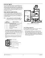
Page 3: ...e connected to the Thermostat input THS on the 35 63J control This should be the only wire attached to the THS terminal The wire from Pin 4 connects directly to the 24VAC Com mon The wire from pin 5 should be connected directly to the Thermostat call for heat signal and not to the 35 63J control Figure 1 Wire Sideview of Plug Figure 2 Vent Damper Wiring Diagram VENT DAMPER CHECKOUT During the chec...

Page 4: ...light because the gas is shut off 4 Turn off the thermostat 5 Turn on the gas supply and purge the gas lines of air Check for gas leaks on all joints upstream of the gas valve with a soap solution 6 Turn the thermostat to a setting high enough to initiate a call for heat Verify the ignition control proceeds through the operating sequence to a normal run burner lit condi tion Confirm there are no g...

Page 5: ...as valves are de energized 2 The control then goes through an interpurge delay before another ignition attempt 3 The control attempts two additional ignition trials before going into lockout and the pilot and main gas valve relays are de energized immediately 4 The LED indicates the fault code for ignition lockout LOCKOUT RESET Recovery from lockout requires a manual reset by either recy cling the...

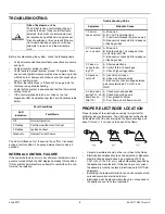
Page 6: ...ve a gap spacing of 0 125 0 031 inch 3 12 0 81 mm unless otherwise specified by the appliance manufacturer If this spacing is not correct the assembly must be replaced Electrodes are NOT field adjustable Exceeding the temperature limits can cause nuisance lock outs and premature electrode failure Electrodes must be placed where they are not exposed to the appliance user in normal operation WARNING...

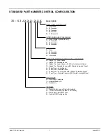
Page 7: ... Local Sense with 5 Minute Automatic Reset 8 Three Tries Remote Sense with 5 Minute Automatic Reset PRE PURGE 0 None 1 15 Seconds 2 30 Seconds 4 4 Seconds INTER PURGE RECYCLE DELAY 0 None Single try models only 1 15 Seconds 2 30 Seconds 3 45 Seconds TRIAL FOR PILOT IGNITION 1 8 Seconds 3 25 Seconds 5 50 Seconds 7 85 Seconds 8 120 Seconds ENCLOSURE 0 Noryl Gray Enclosure 1 Integral Stand Offs 2 Boa...

Page 8: ...Fenwal Inc A UTC Fire Security Company 400 Main Street Ashland MA 01721 Tel 800 FENWAL 1 Fax 508 881 7619 www fenwalcontrols com 06 237172 001 Rev AA 2011 Kidde Fenwal Inc 8 DIMENSIONS Figure 5 Control Dimensions with Cover ...

Reviews: