Preliminary 12/19/01
2
3.
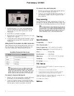
Drill a hole using a 3/16” bit at each mounting hole
location. Make a hole at the base opening location to
run the wires from the HVAC thermostat to the RF
Thermostat.
4.
Install the two wall anchors supplied.
5.
Mount the base to the wall using the two #6 x 1/2” self-
tapping screws supplied.
6.
Create a hole in the wall in the Wire Opening to run the
wiring from the existing HVAC thermostat to the RF
Thermostat.
Wiring the RF Thermostat to the HVAC thermostat:
Some thermostats control heating and cooling, others con-
trol only heating. A heating/cooling thermostat uses four
wires and a heating-only thermostat usually has two.
Note
If the thermostat wire colors are different than those
described above, contact a qualified HVAC service
person for wiring information about your specific ther-
mostat. Be sure to give the service person the manu-
facturer name and model number of the thermostat.
To connect a four-wire thermostat:
1.
Remove the red wire (power feed) from the thermostat
and connect it to the RF Thermostat terminal 1.
2.
Connect a 22-gauge or larger wire from the RF Ther-
mostat terminal 2, to the thermostat terminal where the
red wire (power feed) was previously connected.
To connect a two-wire thermostat:
1.
Remove one of the wires from the thermostat and con-
nect it ot the RF Thermostat terminal 1.
2.
Connect a wire from the RF Thermostat terminal 2, to
the thermostat terminal where the original wire had
been connected.
Programming
For information on operating, programming, testing, and
deleting an RF Thermostat from panel memory, please refer
to your Simon 3 Installation Instructions or User’s Manual.
Note
The RF Thermostat must be installed and powered up
for a minimum of 15 minutes before adjusting its tem-
perature to ensure consistent readings between it and
the house thermostat. For best results, wait an hour
before adjusting the RF Thermostat temperature.
Testing
Specifications
Compatibility: ............ Simon 3
Power Requirements: ?
Storage Temperature: -30° to 140°F (-34° to 60°C)
Operating Temperature: 32° to 140°F (0° to 60° C)
Color: .......................... Belgian Gray
Case Material:............. ABS Plastic
Dimensions: ................ 3.75” x 5.5” x 1.2” (L x W x D)
Installation: ................ Wall mounting
UL Listings: ................
FCC Notice
This device complies with FCC Rules Part 15. Operation is subject to the
following two conditions:
1.
This device may not cause harmful interference.
2.
This device must accept any interference that may be received,
including interference that may cause undesired operation.
Changes or modifications not expressly approved by Interlogix, Inc. can
void the user’s authority to operate the equipment.
FCC ID: B4Z-798A-THERM
Notices
Four-Wire Thermostat Color Code
Wire
Function
Red
Power feed to thermostat
Green
Fan control
Yellow
Cooling
White
Heating


