95-8401
21
2.1
existing filter from the housing, then replace it with a
new filter. Use care not to over tighten.
NOTE
A dirty hydrophobic filter can adversely affect the
response of the sensor by blocking the flow of gas
to the sensing element. If the detector cannot be
calibrated or responds slowly to the calibration gas,
check the condition of the hydrophobic filter before
replacing the sensing element assembly. The
hydrophobic filter should be clean and squarely
seated in the housing.
SENSING ELEMENT REPLACEMENT
The area must be de-classified or power to the sensor
must be removed prior to replacing the sensing
element in a hazardous area.
To replace the sensing element:
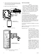
1. If the controller will remain powered during sensor
replacement, enter the sensor replacement mode
by pressing and holding the RESET button for
approximately 9 seconds until the digital display
begins fl ashing and the CAL LED is illuminated.
Release the RESET button.
2. Press the SET button. The FAULT LED also
comes on. The controller is now in the Sensor
Replacement mode.
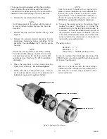
3. Remove the cap from the sensor housing. See
Figure 6. (There is no need to remove the sensor
housing from the junction box.)
4. Remove and discard the old sensing element
assembly. Check for corrosion or contamination
on the terminals inside the sensor enclosure, and
clean if necessary.
5. Determine proper orientation for the new assem-
bly, then
carefully
plug it in.
NOTE
Handle the sensing element assembly carefully.
To avoid possible damage, observe the normally
accepted procedures for handling electrostatic
sensitive devices. See form 75-1005 for additional
information.
6. Place the cap back on the sensor housing.
Tighten only until snug.
Do not over tighten.
7. Re-apply power. Allow time for the unit to warm
up and stabilize (approximately one hour for best
results), then calibrate.
NOTE
If power was removed from the controller during
the sensing element replacement procedure, the
controller will automatically return to the Normal
mode when power is restored (after a time delay).
To prevent the possibility of alarms, allow the
system to warm up in the sensor replacement
mode. The sensor replacement mode can be
entered during the power-up time delay by holding
the RESET button for 7 seconds.
If performing a transmitter calibration, leaving the
controller in the Sensor Replacement mode until after
the calibration is complete will prevent any alarms.
If using the controller calibration method, exit the
Sensor Replacement mode and calibrate.
Press RESET to exit the Sensor Replacement mode.
The controller will enter the Normal mode after a time
delay.
An adequate supply of spare sensing element
assemblies should be kept on hand for field
replacement. For maximum protection against
contamination and deterioration, they should not
be removed from the original protective packaging
until the time of installation. To ensure maximum
storage life, sensing elements should be stored at a
temperature between 32° and 68°F (0 to 20°C) and a
relative humidity between 15 and 90 percent.
NOTE
The sensing element assembly contains an acid
that occasionally can leak. If leakage should
occur, gloves should be worn when handling
the assembly. If acid comes in contact with the
skin, wash the affected area thoroughly with soap
and water. Dispose of all old sensing elements
properly, even if leakage is not detected. Never
attempt to open the sensing element assembly.
Controller Calibration
If transmitters are being used and the system is
being calibrated using the “Controller Calibration”
method, the most accurate calibration for a new
sensor will be achieved if a transmitter calibration
is performed first (as soon as the sensor output has
stabilized). Then perform the “Controller Calibration”
procedure described in the “Calibration” section of
this manual (24 hours later for maximum accuracy).
The controller calibration procedure can then be used
for all subsequent calibrations.
Refer to the “Calibration” section of this manual for the
recommended calibration schedule for a new sensor.
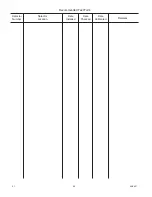
A Recommended Test Form is supplied at the back of
this manual for recording maintenance performed on

