


95-8401
15
2.1
PREMIUM CONTROLLER
The relay outputs (terminals 9 to 16) are programmed
for the desired operation using the procedure
described in the “Controller Programming” section of
this manual.
BASE CONTROLLER
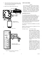
Connections to open collector transistor outputs are
made at terminals 10, 12, 14, and 16. Terminals 9,
11, 13, and 15 are not used. See Figure 14 for an
example of a typical connection to an open collector
transistor output.
NOTE
External equipment that can generate transients
when switching (such as relays) must have a
transient suppression device (diode) properly
connected across the coil at the time of installation.
This will safeguard the output transistors of the
controller against possible damage. Figure 14
illustrates an inductive load with a diode used for
transient suppression.
CONTROLLER PROGRAMMING
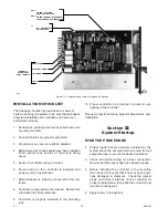
Refer to Figure 15 to determine the location of
programming jumpers and switches. Table 3 shows
the selectable options for each relay.
NOTE
All jumper plugs must be installed. The controller
outputs will not function properly if a jumper plug is
missing.
Normally Open/Closed Relays
The four SPST relays are individually programmed
for either normally open or normally closed contacts.
This is accomplished by placing a jumper plug on
the appropriate pair of pins. Each relay has a set of
three pins. For normally open operation, place the
plug on the NO and center pins. For normally closed
operation, place it on the NC and center pins. The
pin groups are identified as follows:
J2 – High Alarm
J3 – Auxiliary Alarm
J4 – Low Alarm
J5 – Fault
The controller is programmed at the factory for nor-
mally open relay contacts.
NOTE
“Normally Open” or “Normally Closed” refers to
the condition of the relay contacts when “Normally
de-energized” operation is selected. (Refer to
the setting of SW1-2 below.) If the relays are
“Normally Energized,” the condition of the relay
contacts will be reversed.
Latching/Non-Latching Relays
The Low and Auxiliary alarm relays are programmable
for latching or non-latching operation. The High alarm
relay is always latching. Latching relay operation is
programmed using rocker switch 1 at SW1 (SW1-1).
For latching operation, place the switch in the closed
position. For non-latching operation, place it in the
open position. This switch is set at the factory for
non-latching relay operation.
Normally Energized/De-Energized Relays
The three alarm relays are also programmable
for normally energized (fail-safe) or normally de-
energized operation. This is accomplished by
setting rocker switch 2 at SW1 (SW1-2). For normally
energized alarm relays, place the switch in the closed
position. For normally de-energized operation, place
it in the open position. This switch is set at the factory
for normally de-energized operation.
The Fault relay is always normally energized,
regardless of the setting of SW1-2.
NOTE
If the switch positions of SW1 are changed while
power is applied, power must be cycled for the
change to take effect.
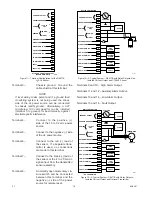
4 to 20 ma Output
Isolated or non-isolated operation of the 4 to 20 ma
output is selected using a jumper plug at J1. For non-
isolated operation, as illustrated in Figure 12, place
the jumper plug in the INT (
int
ernal power source)
position. Place the plug in the EXT position for an
isolated circuit, as illustrated in Figure 13. The jumper
is set at the factory for non-isolated operation.
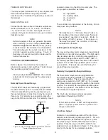
100K
OPEN COLLECTOR OUTPUT
1N4004
TYPICAL
+32 VDC MAXIMUM
B1289
Figure 14—Open Collector Output with Inductive Load and
Transient Suppression Device


