background image

WH-BLE103 Hardware Manual

www.mokuai.cn

Shanghai wenheng electronic technology limited

6 / 10

h.usriot.com

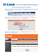
Figure 4 Typical connection

2.2. Power interface

Working voltage range from 1.7V to 3.6V, 3.3V is recommended. Peak current is 30mA. Pin has reserved high
frequency filter capacitance and 10uF+0.1

μ

F+1nf+100pf is recommended. If the application environment is bad,

module will often suffer ESD interference or EMC requirement is high, series connection with magnetic bead or
parallel connection with TVS is recommended to increase module stability.

When user designs the peripheral circuit for BLE103, these should be ensured: 1.Provide adequate power supply.
2.Voltage range from 1.7V to 3.6V. 3.Peak power supply voltage is less than 200mV. 4.Place large capacitance
after DC/DC or LDO to prevent external power supply voltage dropping during pulse current period.

2.3. UART interface

If module adopts 3.3V power supply and communicates to MCU with 3.3V, user just needs to connect TXD of
module to RXD of MCU and RXD of module to TXD of MCU. When communicates to MCU with unmatched
level(such as 5V), switching circuit is necessary. Switching circuit diagram as follow:

Summary of Contents for WH-BLE103

Page 1: ...WH BLE103 Hardware Manual www mokuai cn Shanghai wenheng electronic technology limited 1 10 h usriot com WH BLE103 Hardware Manual File version V1 0 0 01 ...

Page 2: ...al 1 1 Product overview 2 1 1 Dimension 3 1 2 Encapsulation 3 1 3 Pin definition 4 2 Hardware design 5 2 1 Typical connection 5 2 2 Power interface 6 2 3 UART interface 6 2 4 nReset and nReload 7 2 5 Wake up pin 8 2 6 RF interface 8 2 6 1 WH BLE103a 8 2 6 2 WH BLE103b 9 3 Contact 10 4 Disclaimer 10 5 Update History 10 1 Product overview ...

Page 3: ...WH BLE103 Hardware Manual www mokuai cn Shanghai wenheng electronic technology limited 3 10 h usriot com 1 1 Dimension Module dimension diagram as follow Figure 1 Dimension diagram 1 2 Encapsulation ...

Page 4: ... cn Shanghai wenheng electronic technology limited 4 10 h usriot com Figure 2 Encapsulation 1 3 Pin definition PIN Name Signal type Definition 1 nReload I Pull down to low level 3 seconds to 10 seconds can reset module to default settings ...

Page 5: ...xternal antenna 17 GPIO3 IO General IO3 Figure 3 Pin definition Module minimum system can be constituted by VBAT GND UART_TX UART_RX User can also add nReload Wake LINK nReset according to own needs When user adopts external bonding pad pin antenna WH BLE103b user needs to connect RF pin to external antenna ADC GPIO1 GPIO2 GPIO3 are reserved function and user can contact to technical support engin...

Page 6: ...lel connection with TVS is recommended to increase module stability When user designs the peripheral circuit for BLE103 these should be ensured 1 Provide adequate power supply 2 Voltage range from 1 7V to 3 6V 3 Peak power supply voltage is less than 200mV 4 Place large capacitance after DC DC or LDO to prevent external power supply voltage dropping during pulse current period 2 3 UART interface I...

Page 7: ...d take effect in inputting low level nReset pin connects to internal 100K Ohm pull up resistor and also connects to 100nF earth capacitance Press over 100us and release to restart the module nReload nReload pin can connect to external button or configuration pin Press 3 10 seconds to reset to default settings nReload pin connects to internal 10K Ohm pull up resistor Circuit diagram as follows Figu...

Page 8: ...ernal bonding pad pin antenna WH BLE103b 2 6 1 WH BLE103a User needs to follow these rules when adopts WH BLE103a solution 1 On PCB board user can t place component on antenna part as follow red line area Figure 7 WH BLE103a antenna part 2 Keep antenna away from metal maintain a distance at least 10 mm from surrounding high components 3 Antenna must be placed on edge of board 4 Antenna can t be co...

Page 9: ...atch circuit Note 1 Module is recommended to be placed on edge of PCB board to shorten the distance to antenna and this can help to reduce attenuation of signal RF line need guarantee 50ohm impedance matching to avoid lowering signal quality 2 Keep RF line away from power supply clock signal and other signal source which maybe cause interference 3 When user places antenna it is necessary to ensure...

Page 10: ... document provides the information of WH BLE103 products it hasn t been granted any intellectual property license by forbidding speak or other ways either explicitly or implicitly Except the duty declared in sales terms and conditions we don t take any other responsibilities We don t warrant the products sales and use explicitly or implicitly including particular purpose merchant ability and marke...

Reviews: