Page 7
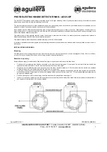
2. Attach the mounting bracket to the electrical junction box using two screws. The screws
are not provided with AC hardwired models. Tighten the screws.
3. Install the alarm on the mounting bracket
4. Insert the pin into the opening located in the base of the alarm (Figure 2)
5. Proceed to the instructions for Stand Alone or Interconnected Alarm Installation.
TO REMOVE:
To remove the alarm after the tamper resistant locking feature has been
engaged; remove the locking pin using long nose pliers. The locking pin is reusable.
IMPORTANT:
Two self-adhesive labels are included with this alarm. On each label write in
the phone number of your emergency responder, for example 911, and a qualified appliance
technician. One label should be placed near where this alarm is installed, and the other label
should be placed in the “fresh air” location you plan to go if the alarm sounds.
WIRING INSTRUCTIONS
Caution! Read Carefully DANGER! ELECTRICAL SHOCK HAZARD
Before beginning installation, turn off main power to the circuit controlling the area where of
this alarm will be wired—at the circuit breaker or fuse box. Failure to turn off the power before
installation may result in serious electrical shock, injury or death.
Make sure the alarm will not receive excessively noisy
power.
Examples of noisy power could be major appliances on the same circuit, power from a gen-
erator or solar power, light dimmer on the same circuit or mounted near fluorescent lighting.
Excessively noisy power may cause damage to the alarm.
This alarm cannot be operated from power derived from a
square wave, modified square wave or modified sine wave
inverter.
These types of inverters are sometimes used to supply power in off-grid installa-
tions, such as solar or wind derived power sources. These power sources may produce high
peak voltages which will damage the alarm.
Installation of this alarm must conform to the electrical codes in your area;
Article 760 of the National Electrical Code, NFPA 72, 101; SBC (SBCCI); UBC (ICBO); NBC
(BOCA): OTFDC (CABO), and any other local or building codes that may apply. Wiring and
installation must be performed by a licensed electrician. Failure to follow these guidelines
may result in injury or property damage.
This alarm must be powered by a 24-hour, 120V AC 60 Hz circuit, 100mA
maximum.
Be sure the circuit cannot be turned off by a switch, dimmer or ground fault cir-
cuit interrupter. Failure to connect this alarm to a 24-hour circuit may prevent it from providing
constant protection.
IMPORTANT:
Do not subject this alarm to megger, high voltage or high-pot tests. Remove
the alarm(s) before high-potting tests occur on the circuit or system. (Ref. Section 550-17,
National Electrical Code, 2014 Edition).
IMPORTANT:
Improper wiring to the AC connector will cause failure to operate, damage to
the alarm, or shock hazard; and will lead to a non-functioning alarm. Never connect the hot
or neutral wires to the yellow interconnect wire. Never cross hot and neutral wires between
interconnected alarms.
STAND ALONE INSTALLATION
IMPORTANT: Read all instructions before using this alarm.
For alarms used as a single, stand-alone, non-interconnected installation, the yellow wire will
not be used. Do not connect the yellow wire to anything. Insulate/tape the end of the wire to
ensure the yellow wire cannot contact any metal parts or junction box.
1. Turn off AC power to the circuit before wiring the AC quick connector
2. There are three pigtail wires (black, white and yellow) in the AC quick connector
3. Using wire nuts, make the connections as follows:
BLACK
“Hot” side of AC line
WHITE
“Neutral” side of AC line
YELLOW
“Interconnect” wire—not used
4. Pull the wiring harness through the center hole in the mounting bracket.
5. Plug the wiring harness into the back of the alarm. It is important to make sure the locking
tabs on the connector snap securely into place.


