8
REVISION 1.0, 1-19-15
7. The sediment filter and carbon must be serviced regularly for optimal performance. The water quali-
ty should be checked every two weeks minimum. The pre-filters should be checked once a month
over the first 3 months of operation to determine the filter change frequency. Typically most appli-
cations will not need to change the filters more than twice annually. However, in some applications
sediment or other contaminants in the feed water may require a more frequent filter change.
8. Dispose of the initial product (clean) water until the TDS level/conductivity of the product water sta-
bilizes at the lowest (cleanest) value. Use any TDS or Conductivity meter to monitor the product wa-
ter quality. A minimum quality of 96% NaCl rejection is recommended (See the rejection rate calcu-
lation).
9.
Once the system has been flushed and the TDS level has stabilized, the permeate/product line can
be attached to the storage tank. Additional flushing of the storage tank and distribution system
may be required to reach the TDS level that is produced directly after the RO system at all points of
use.
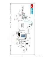
10. This system has been factory wired and preset with a pressure switch at 20 - 40 psi, which is only to
be used with a pressurized bladder tank. If using an atmospheric storage tank, a float switch will be
required to turn the system on and off. An electric float switch can be used. The main power can
be switched by using a “piggy back” connector type float switch or an outlet can be wired to switch
power on and off utilizing a float switch. US Water uses an outlet configuration float switch for the
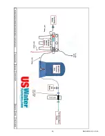
300 GPD RO system. Please see the following typical float diagram and complete system layout.
NOTE: ANY CHLORINE EXPOSURE WILL DAMAGE THE MEMBRANE.
Summary of Contents for L1-200
Page 1: ...1 REVISION 1 0 1 19 15 US Water Systems 300 GPD Premium Wall Mount Light Commercial RO System...
Page 9: ...9 REVISION 1 0 1 19 15...
Page 10: ...10 REVISION 1 0 1 19 15...
Page 11: ...11 REVISION 1 0 1 19 15...
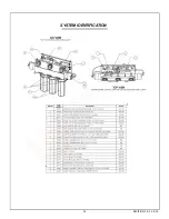
Page 12: ...12 REVISION 1 0 1 19 15 SYSTEM IDENTIFICATION...
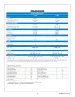
Page 17: ...17 REVISION 1 0 1 19 15 SPECIFICATIONS...
Page 24: ...24 REVISION 1 0 1 19 15 SYSTEM DRAWING...
Page 25: ...25 REVISION 1 0 1 19 15 L1 300 FLOW DIAGRAM...
Page 26: ...26 REVISION 1 0 1 19 15 L1 SERIES ELECTRICAL SCHEMATIC 110V 60HZ...
Page 27: ...27 REVISION 1 0 1 19 15 L1 SERIES ELECTRICAL SCHEMATIC 220V 50HZ...


