background image

40                                                                                             

US Water Aquatrol Water Softener | 076-AQT


Visit us online at www.USWaterSystems.com                                                              Give us a call at: 1-800-608-8792 


WARRANTY 


US  Water  Systems 

warrants  that  your  new  water  conditioner  is  built  of  quality  material  and 

workmanship.  When properly installed and maintained, it will give years of trouble free service. 


Five Year Valve, Electronics and Resin Guarantee 


US  Water  Systems 

will replace any part on the valve or electronics which fails or the softening 

resin within (5) five years from date of manufacture, as indicated by the serial number, provided the 
failure is due to a defect in material or workmanship.  The only exception shall be when proof of pur-
chase or installation is provided and then the warranty period shall be from the date thereof.  Resin 
and internal control valve parts will not be covered for systems used to remove iron, manganese or 
with very high chlorine concentrated feed waters.


Ten Year Warranty on Resin Tank and Brine Tank 


US Water Systems will provide a replacement resin tank or brine tank to any original equipment pur-
chaser in possession of the Aquatrol water softener that fails for (10) ten years after the date of pur-
chase,  provided  that  it  is  at  all  times  operated  in  accordance  with  specifications  and  not  subject  to 
freezing. 


General Provisions 


US Water Systems assumes no responsibility for consequential damage, labor or expense incurred as a result of 
a defect or for failure to meet the terms of these guarantees because of circumstances beyond our control.  In-
stallation workmanship failure is not covered under warranty.  Damage caused by environmental conditions such 
as, lightening strikes, humidity or heat will not be covered under warranty. 
 
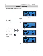
These warranties are in lieu of all other warranties expressed or implied, and we do not authorize any person to 
assume for us any other obligation on the sale of this water conditioner.  No responsibility is assumed for delays 
or failure to meet these warranties caused by strike, government regulations or other circumstances beyond the 
control of 

US WATER SYSTEMS, INC.

 
T

O


OBTAIN


WARRANTY


SERVICE

CALL


OR


WRITE

:  

US WATER SYSTEMS, INC.  1209 C

OUNTRY

 C

LUB

 R

OAD

  I

NDIAN-

APOLIS

,  IN    46234  (317)  271-8600.

  ANY  IMPLIED  WARRANTIES  OF  FITNESS  OR  MERCHANTABILITY  ARE 

LIMITED TO THE TERMS OF THIS EXPRESSED WARRANTY AND THERE ARE NO WARRANTIES WHICH 
EXTEND BEYOND THOSE HEREIN.  

US WATER

  SHALL NOT BE LIABLE FOR ANY INCIDENTIAL OR CON-

SEQUENTIAL DAMAGES. 
 
SOME STATES DO NOT ALLOW THE EXCLUSION OR LIMITATIONS OF INCIDENTAL OR CONSEQUENTIAL 
DAMAGES SO THE ABOVE LIMITATION MAY NOT APPLY TO YOU.  THIS WARRANTY GIVES YOU SPECIF-
IC LEGAL RIGHTS, AND YOU MAY ALSO HAVE OTHER RIGHTS WHICH VARY FROM STATE TO STATE. 
THIS WARRANTY MAY BE TRANSFRRED TO A SUBSEQUENT OWNER WITH WRITTEN APPROVAL OF 

US 

WATER

 AND PAYMENT OF STANDARD TRANSFER FEE.


Aquatrol 

is a product of US Water Systems. 


Summary of Contents for 076-AQT-075

Page 1: ...ner Owners Manual Models 076 AQT 075 076 AQT 100 076 AQT 150 076 AQT 200 REVISION 1 1 REVISION DATE July 19 2016 US Water Systems Corporate Office 1209 Country Club Road Indianapolis IN 46234 Visit us...

Page 2: ...odes 29 Valve Dimensions 31 Assembly Drawings and Parts Lists 32 Valve Wiring 38 Troubleshooting Chart 39 Warranty 40 Table of Contents Check and comply with provincial state and local codes It may be...

Page 3: ...uired by state and federal codes Maximum allowable inlet water pressure is 125 psi If daytime pressure is over 80 psi night time pressure may exceed the maximum Use a pressure reducing valve PRV to re...

Page 4: ...e at www USWaterSystems com Give us a call at 1 800 608 8792 Aquatrol Water Softeners Model Tank Size A B C AQT 075 8 X 44 54 46 8 AQT 100 9 X 48 58 50 9 AQT 150 10 X 54 64 56 10 AQT 200 12 X 52 62 54...

Page 5: ...pipe ALWAYS install the included bypass valve or a 3 shut off valves H valve bypass manifold Bypass valves allow the water to the softener to be by passed for repairs if needed but still have water in...

Page 6: ...equate reserved capacity in place ATTENTION THIS CALCULATION MUST BE COMPLETED TO PROGRAM THE UNIT Total Gallons System Capacity in Grains See chart above Hardness in GPG Grains per Gallon determined...

Page 7: ...f this is not possible be sure to bypass the softener when wa tering grass or plants Chronic soft water exposure can be detrimental to plant life Do not install the softener in a place where it could...

Page 8: ...be free from lime and iron buildup Piping that is built up heavily with lime and or iron should be replaced LOCATION OF AQUATROL TANK AND DRAIN The Aquatrol tank should be located close to a drain to...

Page 9: ...ributed in the tank and pour slow enough to keep from plugging the hole A helper may be needed to hold the funnel during the filling pro cess It is recommended that a dust mask and safety goggles be w...

Page 10: ...g up the tabs then turning the basket clock wise to lock it in place Place the upper basket over the distributor tube and push the valve on the tank Thread the valve on the tank by turning it clockwis...

Page 11: ...ing according to local plumbing codes ON COPPER PLUMBING SYSTEMS BE SURE TO INSTALL A GROUNDING WIRE BETWEEN THE INLET AND OUTLET PIPING TO MAINTAIN GROUNDING Any solder joints being soldered near th...

Page 12: ...than 20 ft linear it is recommended to increase the hose size to 3 4 and be sure there is no sags and a drop in the pip all the way to the drain destination A DIRECT CON NECTION INTO A WASTE DRAIN IS...

Page 13: ...brine line Push the brass tube stiffener in the brine line Install the cone shaped screen in the brass tube stiffener Push the brine line in the brass fitting on the control valve until it stops Then...

Page 14: ...ine tank Remove the cap on the white brine well in the tank and push the brine line through the hole in the side of the tank and brine well 8 Remove the nut and sleeves from the brine safety valve in...

Page 15: ...t 11 Be sure the tube stiffener is in place It may be brass or plastic either can be used Push the brine line in the elbow on the brine safety valve in the brine well until it stops Tighten the nut ha...

Page 16: ...et and let water run a few minutes or until the system is free of any air or foreign material resulting from the plumbing work 14 Make sure there are no leaks in the plumbing system before proceeding...

Page 17: ...of the settings while in the programming mode IMMEDIATE REGENERATION To start an immediate regeneration press and hold the Cycle button Button for 3 5 seconds The valve will start an immediate regener...

Page 18: ...n to drain for 3 4 minutes or un til all media resin fines are washed out of the softener which is indicated by clear wa ter in the drain hose 4 When the backwash cycle is complete the valve will adva...

Page 19: ...tting Button and Up Button simultaneously to enter into Programing Mode Press Up or Down buttons to change hours Press the Settings Button to accept and continue 11 30 11 30 Press Up or Down buttons t...

Page 20: ...Flashing Flashing Default setting is Timer Timer This mode will Not show water capacity options Press Up or Down buttons to change minutes Press the Settings Button to accept and continue Second Step...

Page 21: ...bic Meter Press the Settings Button to accept and continue Gallons Third Step Setting the Unit Capacity Not shown if Timer Mode was selected in 2nd Step Default setting is 1000 Gallons 11 30 SET 3 C U...

Page 22: ...apacity Press the Settings Button to accept cursor moves left and the number flash es Default setting is 1000 Gallons 11 30 0 1000 Gal Flashing Flashing Flashing Flashing 11 30 0 1000 Gal 11 30 0 1000...

Page 23: ...24 hours Set to 336 Use UP or DOWN Buttons to adjust the Regeneration Time 11 30 Set 4 t h Flashing Flashing 11 30 02 H off Flashing Fourth Step Regeneration Time and Hours Override 11 30 02 H off 11...

Page 24: ...2 Set the Time Master Programming Flashing Default setting is 015 Press the Setting Button to accept and continue to next digit 11 30 Set 5 bw Flashing Flashing Flashing Fifth Step Setting the Back Wa...

Page 25: ...tting is 060 Press the Setting Button to accept and continue to next digit Flashing Flashing Flashing Sixth Step Setting the Brine Time Use UP or DOWN Buttons to change Brine time minutes Range 0 999...

Page 26: ...et the Time Master Programming Flashing Default setting is 010 Press the Setting Button to accept and continue to next digit Flashing Flashing Flashing Seventh Step Setting the Rapid Rinse Time Use UP...

Page 27: ...nue to next digit Flashing Flashing Flashing Eighth Step Setting the Brine Fill Time Use UP or DOWN Buttons to change Brine Fill time minutes Range 0 999 Attention Use the table below to determine the...

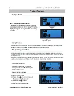
Page 28: ...ime set by the user 11 30 120 gal 11 30 02 18 Backlight Screen Memory during power failure All program settings are stored in permanent memory Current valve position cycle step elapsed time of day are...

Page 29: ...ate a regeneration at the pro grammed regeneration time If it is missed due to power failure it will regenerate on the next day The system will initiate a regeneration either the treated water remaini...

Page 30: ...e button for 5 seconds an im mediate regeneration will be initiated 11 30 Goto bw 11 30 Goto bw 11 30 0 15 bw Examples BW Flashing ready to Backwash When the time counts down to zero or press the butt...

Page 31: ...31 Valve Dimensions 7 5 8 4 1 4 3 3 16 7 7 16 1 3 5 8 4 7 8 4 7 8...

Page 32: ...at www USWaterSystems com Give us a call at 1 800 608 8792 Meter Assembly Item No Quantity Part No Description 1 1 56013 Flow Straightener 2 1 50022 3 Meter Cable Assembly 3 4 01013 O ring 4 1 1220E...

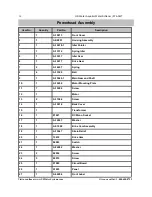
Page 33: ...33 Powerhead Assembly...

Page 34: ...Idler Gear 6 1 A 15617 Drive Gear 7 2 A 14457 Spring 8 4 A 13300 Ball 9 1 A 15622 1 Main Gear and Shaft 10 1 A 15650 Motor Mounting Plate 11 7 A 13296 Screw 12 1 Motor 13 2 A 11384 Screw 14 1 A 15614...

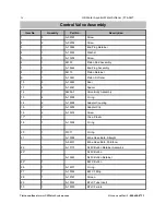
Page 35: ...35 Control Valve Assembly...

Page 36: ...Retainer 9 1 A 13247 Piston Softener 10 5 A 13242 Seal 11 4 A 14241 Spacer 12 1 56256 1 Valve Body Assembly 13 4 A 13305 O ring 14 2 A 19228 Adapter Coupling 15 2 A 13255 Adapter Clip 16 2 A 13314 Sc...

Page 37: ...A 10227 Screen 38 1 A 13163 Injector Body 39 2 A 13301 O ring 40 1 A 13497 Air Disperser 41 1 A 12638 O ring 42 1 A 13302 O ring 43 1 A 13167 Brine Valve Spacer 44 1 A 01003 O ring 45 1 A 13165 A 1255...

Page 38: ...38 US Water Aquatrol Water Softener 076 AQT Visit us online at www USWaterSystems com Give us a call at 1 800 608 8792 Valve Wiring...

Page 39: ...Reconnect the meter cable B Replace the transformer C Replace or repair A Reset timer A reset unit to the new capacity B Keep brine tank full of salt at all times Clean it yearly Salt may be bridged I...

Page 40: ...sibility for consequential damage labor or expense incurred as a result of a defect or for failure to meet the terms of these guarantees because of circumstances beyond our control In stallation workm...

Reviews: