background image

-8-

PANEL CONTROLS

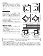
The blowers and automatic fuel supply are controlled from a panel on the top of this unit. The control panel 

functions are a follows.

A. 

ON/OFF SWITCH (“POWER” BUTTON)

• 

When pushed, the stove will automatically ignite. No other fire starter is necessary. The igniter will stay on 

for at least 10 and up to 12 minutes, depending on when Proof of Fire is reached. The fire should start in 

approximately 5 minutes.

• 

The red light located above the “POWER” button will turn green when pressed and remain green until the 

stove is turned off.

• 

After pushing “POWER”, the auger motor is on for 3.5 minutes, off for 1 minute. During the remainder of the 

start-up period, the auger motor operates on the heat range “1” setting.

• 

During start up the heat level advance (Up and Down keys) will change the heat range indicator level 

accordingly, but there is no change in the stoves operating conditions until start-up is completed.

• 

During start-up ignition must occur within 12 minutes or the stove will error out and show E4.

• 

During the start-up phase, the Mode key does not function.

Control Panel

B.  LEVEL / TEMP ARROW BUTTONS

• 

These buttons when pushed will set the pellet feed rate, hence the heat output or heat range of your 

stove. 

• 

The levels of heat output will incrementally change on the bar graph starting from heat range “1” to heat 

range “5”.

C. 

°C / °F Button

• 

The °C / °F button changes the two digit display from degrees Celsius to degrees Fahrenheit.

D.  MODE (M/T) BUTTON

• 

T

he Mode of the stove can be switched between manual and controlled with a Thermostat. Separate 

LEDs to the left of the two digit display indicate the mode of operation – Manual or T-Stat. The stove has 

to be in normal operation to be switched from Manual to T-Stat mode.

• 

Manual mode operates according to the 5 set levels of feed on the bar graph from heat range “1” to 

heat range “5”.

• 

T-Stat mode works as follows:

•  The stove has a built in Thermostat into the controls of the appliance. The temperature sensor for the T-Stat 

is located on the back of the stove behind the display board.

• 

Once the stove has gone into run mode the stove can be switch into T-Stat mode.

• 

The Up and Down Level / Temp Arrow buttons are used to change the desired set-point temperature. 

Once the desired temperature is reached the two digit display will flash for four seconds and reset to the 

actual room temperature.

• 

Once the stove reaches within 3°F of the desired temperature set point, it returns to the heat range that 

the stove was set on before it was switched to T-Stat mode (if the stove was running on heat range “5” 

when switched to T-stat mode when it gets within 3°F of the set point it will return to heat range “5”).

• 

Once the stove reaches the desired set-point, the stove will drop to heat range “1”.

• 

When room temperature drops below desired set-point the stove will ramp back up until it reaches the 

desired temperature.

Summary of Contents for Vogelzang VG5770

Page 1: ...au f tus Pour obtenir plus de renseignements veuillez consulter le site www P65warnings ca gov This manual is subject to change without notice ALL PICTURES SHOWN ARE FOR ILLUSTRATIVE PURPOSES ONLY ACT...

Page 2: ...door open The auger will not feed pellets under these circumstances and a safety concern may arise from sparks or fumes entering the room Allow the stove to cool before performing any maintenance or c...

Page 3: ...ater This heater meets the 2020 US Environmental Protection Agency s wood pellet emissions limits for wood heaters sold after May 15 2020 Under specific test conditions this heater has been shown to d...

Page 4: ...ines must be followed to ensure conformity with both the safety listing of this stove and to local building codes Do not use makeshift methods or compromise in the installation SIDEWALL CLEARANCES PAR...

Page 5: ...thereby reducing exhaust flow and performance of the stove Each elbow or tee reduces draft potential by 30 to 50 All joints in the vent system must be fastened by at least 3 screws and all joints mus...

Page 6: ...er a window or between two windows We recommend Simpson Dura Vent or Metal Fab kits ATTENTION DO NOT vent under any porch deck awning or in any semi enclosed or roofed area Doing so may result in unpr...

Page 7: ...uctions provided with the circuit board COMBUSTION AIR SUPPLY If outdoor combustion air is supplied the heater must be attached to the structure For a mobile home installation the stove must be connec...

Page 8: ...tton The C F button changes the two digit display from degrees Celsius to degrees Fahrenheit D MODE M T BUTTON The Mode of the stove can be switched between manual and controlled with a Thermostat Sep...

Page 9: ...ntroduced by hand will not increase heat output but may seriously impair the stoves performance by generating considerable smoke Do not burn wet pellets The stove s performance depends heavily on the...

Page 10: ...re than a 1 4 of the way If damper is open to far it can cause the fire to go out OPENING DOOR If the door is opened while the stove is in operation it must be closed within 30 seconds or the stove wi...

Page 11: ...tenance on a hot stove Do not operate stove with broken glass leakage of flue gas may result EXHAUST SYSTEM Creosote Formation When any wood is burned slowly it produces tar and other organic vapors w...

Page 12: ...ative that they be cleaned out at a minimum of once per month To access these clean outs you must remove both side panels The clean outs are secured to the firebox with 2 5 16 screws Remove the clean...

Page 13: ...s recommended that you use both smoke and CO monitors in areas having the potential to generate CO CHECK AND CLEAN THE HOPPER Check the hopper periodically to determine if there is any sawdust fines t...

Page 14: ...l silicone spray if your stove is in a high humidity area The exhaust system should be thoroughly cleaned SPRING SHUTDOWN After the last burn in the spring remove any remaining pellets from the hopper...

Page 15: ...ould cause the high limit switch to trip Check to see if a surge protector is being used on the stove If not recommend one to the customer High Limit Switch is malfunctioning If the other items check...

Page 16: ...hen remove the two bolts that hold the auger bracket to the auger tube The auger bracket will now be able to be removed form the auger tube Remove the two bolts on the side of the auger tube to remove...

Page 17: ...er shaft Gently lift the auger shaft straight up so that the end of the auger shaft comes up out of the bottom auger bushing Next remove the two nuts that hold the top auger biscuit in Then rotate the...

Page 18: ...o seal joints with UL 181 AP foil tape Also make sure the square to round adapter piece on the combustion blower has been properly sealed with the same RTV The gasket on the combustion blower has gone...

Page 19: ...ntrol board If the fuse is good the wires and connectors check out good and the high limit switch did not trip test for power going to the auger motor If there is not a full current going to the auger...

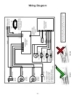
Page 20: ...20 Wiring Diagram CORRECT WRONG Ensure the wires are connected to the bottom two prongs of the hopper switch as shown...

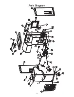
Page 21: ...21 1 2 3 4 8 9 15 17 19 34 20 21 22 23 27 28 29 30 35 36 37 38 40 41 24 25 5 6 7 43 18 26 33 14 1 16 18 39 42 12 13 31 32 Parts Diagram...

Page 22: ...29 892202 Vented Back Panel 1 30 86624 Burnpot 1 31 891121 Hose Silicon 1 32 83537 Hose Clamp 1 33 88176 Insulating Blanket 1 34 88177 Gasket Ash Clean out 2 35 88175 Gasket T disc 2 36 80601 T Disc R...

Page 23: ...7 Date _____________________ Engineer Name ________________________________ License No ____________________________________ Company _____________________________________ Telephone No _________________...

Page 24: ...ice fiable et efficace de votre appareil de chauffage et vous permettre de commander correctement les pi ces de rechange Conservez ce manuel dans un endroit s r pour r f rence future Lors de l criture...

Page 25: ...____________________________ Service de 07 Date _____________________ Nom de l ing nieur ____________________________ N de licence _________________________________ Compagnie _________________________...

Page 26: ...4 pot de combustion 1 31 891121 Hose Silicon 1 32 83537 Collier de serrage 1 33 88176 Couverture isolante 1 34 88177 Joint Ash Clean out 2 35 88175 Joint T disque 2 36 80601 T Disc Chambre Air 1 37 88...

Page 27: ...22 1 2 3 4 8 9 15 17 19 34 20 21 22 23 27 28 29 30 35 36 37 38 40 41 24 25 5 6 7 43 18 26 33 14 1 16 18 39 42 12 13 31 32 Sch ma Des Pi ces...

Page 28: ...21 Sch ma De C blage CORRECT FAUX Assurez vous que les fils sont connect s aux deux broches inf rieures de l interrupteur de la tr mie comme illustr...

Page 29: ...oit bien fix e la tige du registre d admission Lorsqu on d place la tige du registre la plaque doit se d placer avec elle Blocage du conduit d admission d air Inspecter visuellement le conduit d admis...

Page 30: ...locage Fil d branch ou connecteur desserr V rifiez tous les fils et connecteurs branch s sur le moteur de tari re l interrupteur de surchauffe et le connecteur Molex Tableau de commande d fectueux Si...

Page 31: ...branchez le po le avant toute chose quand c est possible Il y a une fuite dans le syst me de conduit d vacuation Inspectez tous les raccords de tuyaux d vacuation Assurez vous qu ils soient tous scel...

Page 32: ...esteur de continuit pour tester l interrupteur de s curit de la tr mie remplacer le si n cessaire L arbre de la tari re est coinc Commencez par vider la tr mie Puis retirez le moteur de la tari re en...

Page 33: ...le moteur tourne c est l arbre qui est coinc sur quelque chose Si le moteur ne tourne pas il est d fectueux Le thermodisque de d tection de feu POF a mal fonctionn Contournez temporairement le thermod...

Page 34: ...des granul s de bois Recherchez la pr sence de combustibles autre que des granul s de bois Aucun autre type de combustible n a t approuv pour ce po le granul s En pr sence de signes d utilisation d au...

Page 35: ...faites fonctionner la tari re jusqu ce que la tr mie soit vide et que les granul s cessent de couler il suffit pour cela d appuyer sur l interrupteur ON en gardant la porte d observation ouverte Pass...

Page 36: ...sciure des fines s est accumul e dans le syst me d alimentation ou si des granul s sont rest s coll s la surface de la tr mie Nettoyez les si n cessaire JOINTS DE PORTE ET DE VITRE Inspectez p riodiq...

Page 37: ...uvent l int rieur des portes du bo tier au niveau des coins inf rieurs ant rieurs de l changeur de chaleur Pour acc der ces outs propres vous devez retirer les deux panneaux lat raux Les sorties propr...

Page 38: ...u nettoyage ou l entretien sur un po le chaud N utilisez pas le po le si la vitre est cass e il pourrait en r sulter une fuite de gaz de combustion SYST ME D VACUATION Formation de cr osote Lorsque le...

Page 39: ...re de tirage doit tre soit compl tement ferm soit ouvert au maximum au quart de sa course Si le registre est trop ouvert le feu pourrait s teindre OUVERTURE DE LA PORTE Si la porte est ouverte pendant...

Page 40: ...roduit la main n augmenterait pas la production de chaleur mais pourrait nuire gravement aux performances du po le en g n rant beaucoup de fum e Ne br lez pas de granul s mouill s Les performances du...

Page 41: ...gramme en barres passant du niveau 1 au niveau 5 de chauffage C TOUCHE C F La touche C F fait passer l affichage deux chiffres des degr s Celsius aux degr s Fahrenheit et vice versa D TOUCHE MODE M T...

Page 42: ...n ext rieur est fourni le chauffage doit tre fix la structure Pour une installation de maison mobile le po le doit tre raccord une source ext rieure d air de combustion A 2 po l int rieur de diam tre...

Page 43: ...N 3 po 76 mm MIN COUDE 90 TERMINAISON CAF FIXATION DE SUPPORT ADAPTATEUR D CHAPPEMENT DU MOTEUR ADAPTATEUR DE TUYAU COUPE FEU MURAL COUVERCLE DE NETTOYAGE PROTECTION DE PLANCHER EN MAT RIAU NON COMBUS...

Page 44: ...es fum es Les coudes 90 degr s accumulent les cendres volantes et la suie r duisant par l m me le d bit de l vacuation et les performances du po le Chaque coude ou T r duit le potentiel de tirage de 3...

Page 45: ...MUR LAT RAL EN CAS D INSTALLATION PARALL LE D GAGEMENT AVEC LE MUR LAT RAL EN CAS D INSTALLATION EN COIN D GAGEMENTS in mm Parall le A Mur arri re l appareil 3 76 B Mur lat ral au conduit de fum e 11...

Page 46: ...ait de la chaleur des taux allant de 9 218 18 619 Btu h Cet appareil de chauffage a atteint un taux d mission de particules de 0 85 g h et une efficacit de 70 La taille des granul s peut influencer le...

Page 47: ...es pas fonctionner le po le lorsque la porte d observation est ouverte Dans ce cas la tari re ne distribue pas les granul s et un probl me de s curit peut se poser en raison des tincelles ou des fum e...

Page 48: ...E L AM LIORATION DU PRODUIT Veuillez lire enti rement ce manuel d installation et d utilisation AVANT de mettre en place et de faire fonctionner votre nouveau po le granul s de bois pour chauffage de...

Reviews: