-4-
CLEARANCES
Your pellet stove has been tested and listed for
installation in residential, mobile home, and alcove
applications in accordance with the clearances
given in this manual. For safety reasons, please
adhere to the installation clearances and restrictions.
Any reduction in clearance to combustibles may
only be done by means approved by a regulatory
authority.
FLOOR PROTECTION
This heater must have a non-combustible floor
protector (UL1618 ember protection) installed
beneath it if the floor is of combustible material. The
floor pad or non-combustible surface should be large
enough to cover at least the area under the product
and 6” (152 mm) beyond the front and beyond each
side of the fuel loading and ash removal openings.
Your heater will need a minimum 31” X 38” floor
protector. Floor protection must extend under and
2” (50.8 mm) to each side of the chimney tee for an
interior vertical installation.
Canadian Installations require a minimum of 475 mm
[18”] beyond the front of the unit and 203 mm [8”]
beyond each side of the unit. A Floor Protector of 1/4
inch thick is recommended for this installation.
VENTING REQUIREMENTS
•
Install vent at clearances specified by the vent
manufacturer.
•
Do not connect the pellet vent to a vent serving
any other appliance or stove.
•
Do not install a flue damper in the exhaust venting
system of this unit.
The following installation guidelines must be followed
to ensure conformity with both the safety listing of
this stove and to local building codes. Do not use
makeshift methods or compromise in the installation.
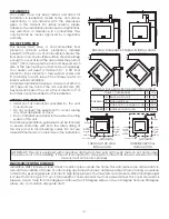
SIDEWALL CLEARANCES PARALLEL INSTALLATION
SIDEWALL CLEARANCES CORNER INSTALLATION
TABLE 1 CLEARANCES
in mm
PARALLEL
A
Back wall to unit
3
76
B Sidewall to flue
11
280
C
Sidewall to top edge of unit
8 203
CORNER D Adjacent wall to unit
8 203
U.S.A 6”
(153 mm)
Canada
8”
(203mm )
U.S.A 6”
(153 mm)
Canada
8”
(203mm )
U.S.A 6”
(153 mm)
Canada
8”
(203mm )
U.S.A 6”
(153 mm)
Canada
8”
(203mm )
U.S.A 6” (153 mm)
Canada 8” (203mm )
Floor Protector
U.S.A 6” (153 mm)
Canada 8” (203mm )
Floor Protector
1”
(25 mm)
2”
(50 mm)
THROUGH THE WALL
INSTALLATION
INTERIOR VERTICAL
INSTALLATION
IMPORTANT! This unit is equipped with a negative draft system that pulls air through the burn pot and pushes
the exhaust out of the dwelling. If this unit is connected to a flue system other than the way explained in this
manual, it will not function properly.
MAXIMUM VENTING DISTANCE
Installation MUST include at least 3-feet of vertical pipe outside the home. This will create some natural draft to
reduce the possibility of smoke or odor during appliance shutdown and keep exhaust from causing a nuisance
or hazard by exposing people or shrubs to high temperatures. The maximum recommend vertical venting height
is 12-feet for 3-inch type “PL” vent. Total length of horizontal vent must not exceed 4-feet. This could cause back
pressure. Use no more than 180 degrees of elbows (two 90-degree elbows, or two 45-degree and one 90-degree
elbow, etc.) to maintain adequate draft.

