11
E N G L I S H
1. INTRODUCTION
This Meter is a handheld and battery
operated instrument that is designed and
tested according to IEC Publication 1010
(Overvoltage Category lll) and other safety
standards (see “Technical Data”).
WARNING: READ “SAFETY
CONSIDERATIONS” BEFORE USING
THIS METER.
2. SAFETY CONSIDERATIONS
Before using this Meter, read the following
safety information carefully. In this manual,
the word “WARNING” is used for conditions
and actions that pose hazard(s) to the user;
the word “CAUTION” is used for conditions
and actions that may damage this Meter.
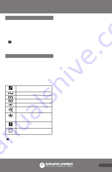
International Symbols.
WARNING Dangerous Voltage
(Risk of electric shock)
Alternating Current (AC)
Direct Current (DC)
Either DC or AC
Diode
Capacitor
Ground (Allowable applied
voltage range between the
input terminal and earth
CAUTION Refer to the user’s
manual before using this Meter
Double Insulation (Protection
Class II)
WARNING: OBSERVE ALL SAFETY
PRECAUTIONS WHEN MEASURING
HIGHER VOLTAGES. TURN OFF POWER
TO THE CIRCUIT UNDER TEST, SET THIS
METER TO THE DESIRED FUNCTION AND
RANGE, CONNECT THE TEST LEADS TO
THIS METER AND THEN TO THE CIRCUIT
UNDER TEST. REAPPLY POWER. IF AN
ERRONEOUS READING IS OBSERVED,
DISCONNECT POWER IMMEDIATLY
AND RECHECK ALL SETTINGS AND
CONNECTIONS.
Safety Tips.
Exceeding the specified limits of this Meter
is dangerous, and can expose the user to
serious and possibly fatal injury. To ensure
safe and appropriate use, please follow the
safety guide lines below:
• Do not try to measure any voltage that
exceeds 750 DC V or 750 AC V peak.
• Voltages above 60 V DC or 25V AC RMS
may constitute a serious shock hazard.
• Do not attempt to use this Meter if either
the Meter or the test leads have been
damaged.
• Turn off power to the circuit under test
before cutting, unsoldering, or breaking
the circuit. Small amounts of current can
be dangerous.
• Disconnect the live test lead before
disconnecting the common test lead.
• When using the test leads, keep your
fingers behind the finger guards on the
probes.
Features.
• 3 ¾ digit, 4000 count LCD with 41 segment
bar graph
• Auto Range or Manual Range Selection
• Standby Mode Indicator
• Data Hold
• Logic Probe Function
• Capacitance Measurement
• Frequency Measurement
• Fast Continuity Beeper
• Diode Test
Summary of Contents for UD18
Page 18: ...18 NOTAS NOTES...
Page 19: ...19 NOTAS NOTES...


