background image

Urban Fires UF950RC Installation & Use Instructions V3.8 April 2018 Page  6  

2.0 Power Supply for ignition:  


This appliance should only be operated by the 6v transformer supplied, from a 240v supply.  

In an emergency, such as a power or transformer failure, 4 x AA size batteries can be used for ignition. 

These can be located into the Receiver Unit inside the control box under the IP-rated cover but MUST 

NOT be used at the same time as transformer power. 

2.1 Installing Batteries:  

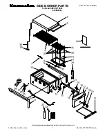
To install batteries, the complete burner assembly must be lifted out from its housing (i.e firebox, firetable, 
etc). The gas supply is connected via a flexible supply hose. Remove the control lid cover to gain access to 
the Receiver Unit pictured above. To remove the cover of the Receiver Unit itself pull the cover back. Ensure 
the batteries are placed in the correct orientation. Disconnect the transformer. 

Once batteries have been placed inside, replace the cover and seal the IP-rated Control Box assembly 

2.2 Normal Power Source: (Supplied transformer) 

To connect the UF950RC to 240v mains electricity 
instead of using batteries for ignition, you should do so 
using the transformer supplied.  

Route the transformer cable through the side of the 
housing via one of the bungs supplied to protect 
against moisture damage. The bung will need to be 
punctured to enable this. Remove the batteries and 
connect the transformer to the fire by plugging the 
connector of the transformer into the Receiver Unit. 

Use some silicon to seal the bung where the cable 
passes through the bung. 

The transformer will require a 240v supply and a standard 3-pin socket and MUST BE contained 

within a suitable IP-rated waterproof enclosure. (Not supplied).

Here are details of a suitable enclosure:

http://www.tlc-direct.co.uk/Products/GWBX645.html

You will need the following components:

- GWBX645 150 x 110 x 140mm IP56 Moulded Box
- EK241B 13mm Nylon Compression Gland Black for Cable 5-7mm 
- EK79B 13mm Nylon Lock Ring - Black

Summary of Contents for UF750RC

Page 1: ...S NOT SUPPLIED PP3 REQUIRED The appliance shall be installed in accordance with This installation instruction booklet Local gas installation regulations and The Rules in Force BS 5440 1 BS 5871 1 2005...

Page 2: ...ireboxes firetables and firepits but site contractors must be aware that suitable ventilation to and drainage from any masonry construction is required to prevent pooling of water within the enclosure...

Page 3: ...the burner 11 10 0 Fixing the burner into the fireplace 11 11 0 Connecting the Switch Panel 12 12 0 Testing of the power switch ignition 12 13 0 Placement of ceramic fire media 12 14 0 User Instructio...

Page 4: ...ebox firepit or firetable see www urbanfires co uk The fire is operated by a remote handset The handset controls a series of electronic circuits to operate 1 the ignition sequence 2 up down control of...

Page 5: ...Urban Fires UF950RC Installation Use Instructions V3 8 April 2018 Page 5 1 2 Technical Data Please note that this appliance is for decorative purposes You cannot cook on this appliance...

Page 6: ...ce batteries have been placed inside replace the cover and seal the IP rated Control Box assembly 2 2 Normal Power Source Supplied transformer To connect the UF950RC to 240v mains electricity instead...

Page 7: ...ger made to measure burner trays can be provided by Urban Fires Fireboxes supplied by Urban Fires will be made with a suitable burner tray and rebated cutout 3 1 Burner cut out dimensions The objectiv...

Page 8: ...l directly above the heater does get hot and hence may discolour certain exte rior paint finishes 4 2 Some exhaust stains may also become visible directly above the fire due to exhaust of products of...

Page 9: ...ative building standards Typically an outdoor space is not enclosed but any enclosure in which the appliance is used should comply with one of the following 6 1 An enclosure with walls on all sides bu...

Page 10: ...ated in a corner the following drawings give the minimum sized interior wall dimensions possible 7 2 Allowances should be made for cladding the internal sides of the cavity 7 3 Dimensions of the cavit...

Page 11: ...he gas supply should be properly located away from pathways or areas where the hose may be subject to accidental damage If in doubt use Tracpipe 9 0 Connecting the Gas Supply to the UF950RC outdoor ga...

Page 12: ...ng instructions 13 0 Placement of the Crystalight moulded ceramic glass gas fire media 13 1 Two or four 30mm x 30mm stainless steel plates are supplied to cover the finger holes before placing the Cry...

Page 13: ...r weathercover to order To fit the optional weathercover ensure the fire is off and cooled The fire MUST NOT be operated while the cover is fitted The cover MUST NOT be fitted while the fire is hot A...

Page 14: ...Ensure the MANUAL knob on the Mertik GV60 gas control valve is turned to ON full counter clockwise position and if supplied the ON OFF switch is switched the ON position When the Burner is extinguishe...

Page 15: ...Urban Fires UF950RC Installation Use Instructions V3 8 April 2018 Page 15 Pairing the remote handset...

Page 16: ...s the top of the burner Do not allow the media to enter the pilot light assembly at any time as this can cause failure of the ignition system 15 0 Maintenance and Cleaning 15 1 The complete unit must...

Page 17: ...g the handset can you hear the motorised gas valve re setting If not you can reset the ignition process electronic controls and motorised gas valve by turning off the 240V supply waiting 30 seconds sw...

Page 18: ...Urban Fires UF950RC Installation Use Instructions V3 8 April 2018 Page 18 17 0 Burner Replacement Parts...

Page 19: ...Urban Fires UF950RC Installation Use Instructions V3 8 April 2018 Page 19 18 0 Control Box replacement parts...

Page 20: ...ppliance is set for use on Natural Gas G20 at a supply pressure of 20mbar or Propane G31 at a supply pressure of 37mbar and Butane G30 at 28 30mBar The conversion kit consists of one 1 main burner inj...

Page 21: ...own below Next change the NG injector for the LPG injector by using a split 17mm ring spanner for convenience disconnecting the gas supply tube first DO NOT REPLACE THE AERATION COVER PLATE Ideally co...

Reviews: