background image

5

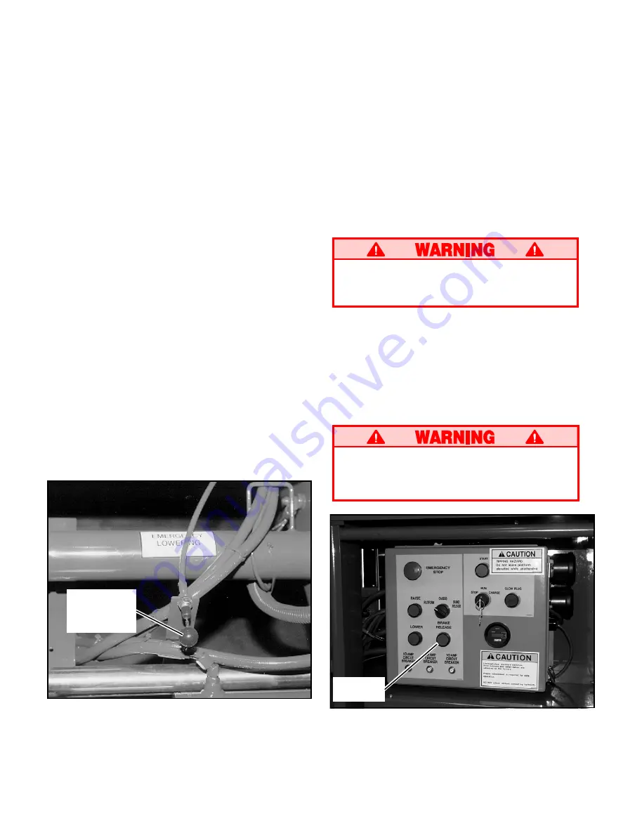
Figure 4: Emergency Lowering Knob

After Use Each Day

1. Ensure that the platform is fully lowered.
2. Park the machine on level ground, preferably

under cover, secure against vandals, children

or unauthorized operation.

3. Turn the key switch to 

OFF 

and remove the

key to prevent unauthorized operation.

Parking Brake Release (Figure 5)

Perform the following only when the machine will

not operate under its own power and it is neces-

sary to move the machine or when winching onto

a trailer to transport.

Never release brakes if machine is on a

slope. Hook machine to towing vehicle

before releasing brakes.

1. Turn  Platform/Chassis/Brake  Release  switch

to Brake Release position. Alarm will sound.

2. Momentarily push brake Release button.
3. The machine will now roll when pushed or

pulled.

4. For normal operation, turn Platform/Chassis/

Brake Release switch to Platform position.

Never operate work platform with the

parking brakes released. Serious injury or

damage could result.

Travel with Work Platform Elevated

Travel with platform elevated 

ONLY 

on firm and

level surfaces.

Note: The work platform will travel at reduced

speed when in the elevated position, and only

when the front axle is parallel with the rear axle.

1. Check that the route is clear of persons, ob-

structions, holes and drop-offs, surface is level

and capable of supporting the wheel loads.

2. Check clearances above, below and to the sides

of platform.

3. Position the drive/lift switch to the 

DRIVE

position.

4. Push the control lever to 

FORWARD 

or 

RE-

VERSE 

for the desired direction of travel.

If the machine quits driving and the tilt alarm

sounds, immediately lower the platform and

move the machine to a level location before re-

elevating the platform.

Emergency Lowering

The emergency lowering knob is located at the

front of the machine at the base of the scissor

assembly (Figure 4).

1. Open the emergency lowering valve by pulling

on the knob and holding it.

2. Once the platform is fully lowered, release the

knob to close the valve.

Emergency

Lowering

Knob

Brake

Release

Figure  5:  Parking  Brake  Release  Button

All manuals and user guides at all-guides.com

Summary of Contents for LX Bi-Energy

Page 1: ...er mounting platform KEEP all body parts clear of outriggers when extending or retracting outrigger equipped machines only NEVER use ladders or scaffolding on the platform NEVER attach overhanging loads or increase platform size MAINTAIN tire pressure at 50 psi Check daily LOOK up down and around for overhead obstructions and electrical conductors DISTRIBUTE all loads evenly on the platform See th...

Page 2: ...tes freely and latches securely 7 Check tires for damage Check tire pressure 75 psi 5 2 bar if equipped with pneumatic tires 8 Carefully inspect the entire work platform for damage such as cracked welds or structural members loose or missing parts oil leaks damaged cables or hoses and loose connec tions 9 Bi Energy models While the engine is cool check the engine coolant level NEVER remove the cap...

Page 3: ...elevate and or there is no alarm STOP and remove the machine from service until it is repaired 9 Release the tilt sensor and fully elevate platform Figure 2 Controller 10 Visually inspect the elevating assembly lift cylinder cables and hoses for damage or erratic operation Check for missing or loose parts 11 Lower the platform partially by pushing in on the chassis lower switch and check operation...

Page 4: ... platform ensure that the pre operation and safety inspection has been completed any deficiencies have been corrected and the operator has been thoroughly trained on this machine NOTE Bi Energy machine may be powered by batteries or by engine To power the machine by engine press engine start button to crank the engine Release button when engine starts If engine is cold press the glow plug button o...

Page 5: ... could result Travel with Work Platform Elevated Travel with platform elevated ONLY on firm and level surfaces Note The work platform will travel at reduced speed when in the elevated position and only when the front axle is parallel with the rear axle 1 Check that the route is clear of persons ob structions holes and drop offs surface is level and capable of supporting the wheel loads 2 Check cle...

Page 6: ...he side guardrails 3 Raise rear guardrail assembly aligning holes and install bolts washers and nuts 4 Raise front guardrail aligning holes and install bolts washers and nuts 5 Hang controller on front guardrail 6 Before operating work platform check that all fasteners are in place and properly torqued Before operating machine guardrails must be securely fastened in their proper position Double De...

Page 7: ...hart on page 10 1 Raise front guardrail making sure it is pushed down to secure the guardrail in the vertical position Repeat for rear guardrail 2 Raise guardrails making sure each is pushed down to secure the guardrail in the vertical position Align holes and install hardware 3 Raise one of the four slide out deck side guard rail assemblies Align holes and install hardware Repeat this procedure f...

Page 8: ...2 Rotate scissors brace clockwise until the locking pin engages Verify locking pin is engaged 3 Lower platform completely Battery Maintenance Hazard of explosive gas mixture Keep sparks flame and smoking materials away from batteries Always wear safety glasses when working with batteries Battery fluid is highly corrosive Rinse away any spilled fluid thoroughly with clean water Always replace batte...

Page 9: ...eration Daily Control Checktheexteriorofthecable Daily Cable forpinching bindingorwear Platform Checkfastenersforpropertorque Daily Deckand Checkweldsforcracks Daily Rails Checkconditionofdeck Daily Tires Checkfordamage Daily Checkairpressure 75psi 5 2bar Daily Check lug nuts torqueto150ft lbs 205Nm 30D Hydraulic Wipeclean 30D Pump Checkforleaksatmatingsurfaces 30D Checkforhosefittingleaks Daily C...

Page 10: ...10 NOTES All manuals and user guides at all guides com ...

Page 11: ...Part Number located by each label For machines equipped with options consult Service Manual 67638 002 1 REQUIRED BI ENERGY MODELS ONLY 66555 000 1 REQUIRED 66551 002 1 REQUIRED 66555 000 1 REQUIRED 62562 002 1 REQUIRED 66558 000 2 REQUIRED 66561 001 1 REQUIRED 27898 000 1 REQUIRED BI ENERGY MODELS ONLY 66568 000 1 REQUIRED 66552 000 1 REQUIRED 66550 009 1 REQUIRED 66554 000 00 1 REQUIRED 61515 001...

Page 12: ...6 m x 1 73 m 228 in x 68 in 5 79 m x 1 73 m 2000 lbs 907 kg 2000 lbs 907 kg 500 lbs 227 kg 1750 lbs 795 kg 500 lbs 227 kg 8 people 2 people 8 people 2 people 37 ft 11 28 m 31 ft 9 45 m 56 3 in 1 43 m 2WD 9 920 lbs 4 500 kg 2WD 10 120 lbs 4 590 kg 2WD 10 350 lbs 4 695 kg 2WD 10 550 lbs 4 785 kg 2WD 10 780 lbs 4 890 kg 2WD 10 980 lbs 4 981 kg 90 in 2 29 m 99 75 in 2 53 m 160 5 in 4 08 m 31 ft 9 45 m...

Reviews: