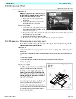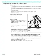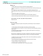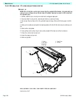
Page 3-5
Maintenance
3.4 - Battery Maintenance
TL50 Service & Parts
C
HARGE
BATTERY
AS
FOLLOWS
:
1. Check the fluid level. If the electrolyte level is lower than 10mm (3/8 in.) above the plates,
add clean, distilled water only.
2. Connect the charger plug to a properly grounded outlet of the proper voltage and frequency.
3. The charger turns on automatically after a short delay. The ammeter will indicate DC charg-
ing current.
4. The charger turns off automatically when the batteries are fully charged.
B
ATTERY
C
ELL
E
QUALIZATION
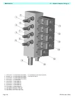
Figure 3-2: Power Module
The specific gravity of the electrolyte in the bat-
tery cells should be equalized monthly. To do
this, charge the batteries as outlined in Battery
Charging. After this initial charge, check the
electrolyte level in all cells and add distilled
water as necessary. Turn the charger on for an
additional eight hours. During this time, the
charging current will be low (four amps) as cells
are equalizing.
After equalization, the specific gravity of all cells
should be checked with a hydrometer. The tem-
perature corrected specific gravity in this state
should be 1.260. If any corrected readings are
below 1.230, the batteries containing such cells
should be replaced.
Do not check the specific gravity in a cell to which water has just been added. If there is not
enough electrolyte in a fully charged cell to obtain a sample for the hydrometer, add water and
continue charging for one to two hours to adequately mix the water and electrolyte.
W A R N I N G
!
!
Charge the battery only in a well-ventilated area.
Do not charge the battery when the work platform is in an area containing
sparks or flames.
Permanent damage will result if the battery is not immediately recharged
after discharging.
Never leave the charger unattended for more than two days.
Never disconnect the cables from the battery when the charger is operating.
Keep the charger dry.
Never operate the machine while the charger is plugged in.
Remove to check
fluid
Summary of Contents for 503502-000
Page 1: ...ERVICE PARTS MANUAL POWERED ACCESS WORK PLATFORM TL50...
Page 21: ...Page 16 TL50 Service Parts Specifications Notes...
Page 51: ...Page 3 30 Maintenance 3 19 Torque Specifications TL50 Service Parts NOTES...
Page 59: ...Page 5 2 Schematics 5 1 Introduction TL50 Service Parts...
Page 60: ...Page 5 3 Schematics 5 1 Introduction TL50 Service Parts...
Page 61: ...Page 5 4 Schematics 5 1 Introduction TL50 Service Parts...
Page 62: ...Page 5 5 Schematics 5 1 Introduction TL50 Service Parts...
Page 63: ...Page 5 6 Schematics 5 1 Introduction TL50 Service Parts Notes...
Page 66: ...Page 6 3 Illustrated Parts Breakdown General Assembly TL50 Service Parts 1 1 2 3 4 5 6 7...
Page 70: ...Page 6 7 Illustrated Parts Breakdown Booms Posts Assembly TL50 Service Parts 44 45...
Page 72: ...Page 6 9 Illustrated Parts Breakdown Platform Assembly Standard TL50 Service Parts...
Page 74: ...Page 6 11 Illustrated Parts Breakdown Platform Assembly Rotator TL50 Service Parts...
Page 88: ...Page 6 25 Illustrated Parts Breakdown Hydraulic Tank Assembly TL50 Service Parts...
Page 90: ...Page 6 27 Illustrated Parts Breakdown Electrical Assembly TL50 Service Parts...
Page 92: ...Page 6 29 Illustrated Parts Breakdown Hydraulic Assembly TL50 Service Parts...
Page 94: ...Page 6 31 Illustrated Parts Breakdown Decal Assembly TL50 Service Parts...
Page 95: ...Page 6 32 Illustrated Parts Breakdown Decal Assembly TL50 Service Parts...
Page 96: ...Technician s Print TL50 W ork Platform Electrical Schematic...
Page 97: ...Technician s Print TL50 W ork Platform Harness Schematic...
Page 98: ......


