background image

18  l  Uponor Comfort Port EU  l  Technical Information

EN

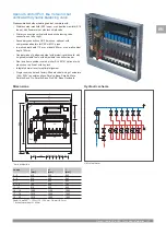
Hydraulic scheme

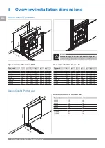
Dimensions

HM

HM = Heat meter

215 (225*)

260

90

56 50

270

50 50 50 50

110

Rp ¾

Rp ¾

G ¾

G ¾

0 - 200

l

1

nl

l

690

560

**

* Vario M Manifold   ** Optional: balancing valve or diff. pressure control valve

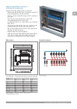
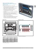
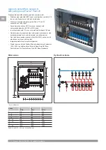
Uponor Comfort Port, Version 4:  

horizontal with metering set

Preassembled underfloor heating cabinet, complete with:
•  Stainless steel manifold (2-20 loops), or polyamide manifold (2-15 

loops), with flowmeters or with lock shield valve

•  Primary connection horizontal with metering set G3/4, connection 

on left or right

•  Secondary connections G3/4 Eurocone, optional: with 

compression adapters for PEX or MLC pipes

•  In-wall cabinet depth 110 mm, or depth 80 mm, or on-wall cabinet 

depth 140 mm

•  Cabinet made of galvanized steel with protective cardboard, with 

height-adjustable feet’s, with adjustable tube deflection bar

•  Door and frame powder coated, white (RAL 9016), optional: with 

plastic door, optional: with key lock

•  Integrated water level for optimal alignment
•  Single room control and factory-fitted electrical wiring of actuators 

(24 or 230V), possible options: Smatrix Base, Smatrix Wave, 
Smatrix Base Pro, Smatrix Base Pro KNX, Base Flexiboard

Depth: In-wall 95** – 120 or 110 – 150 mm, On-wall 140 mm

** by heat meter depth > 95mm

Loops

l

1


[mm]

nl 

[mm]

[mm]

2 – 3

610

650

643

4 – 6

760

800

793

7 – 9

910

950

943

10 – 12

1060

1100

1093

13 – 15

1210

1250

1243

16 – 20

1510

1550

1543

Summary of Contents for Comfort Port EU

Page 1: ...Uponor Comfort Port EU EN Technical Information...

Page 2: ...4 1 4 Cost comparison 5 1 5 Variances and configuration examples 5 1 6 Components 8 2 Configuration and calculation 9 2 1 Web Configurator 9 3 Installation and Operation 10 3 1 Design requirements 10...

Page 3: ...all to the building site Reduction of installation time pre wired actuators and control units or marking of loops are only few of the advantages of preassembling in Uponor factory which avoids signifi...

Page 4: ...r Comfort Ports virtually eliminates the likelihood of something going wrong on the job site All actuators are assigned to the respective heating zones labeled and placed on the control terminal block...

Page 5: ...s installation time About 9 800 different configuration can be assembled to one complete Comfort Port unit All they base and consists on general components which ensure the perfect functionality This...

Page 6: ...w o metering set Uponor Vario S Manifold 6 loops with ball vale 3 4 horizontal connection In wall cabinet Horizontal with metering set Uponor Vario S Manifold 6 loops with metering set 3 4 horizontal...

Page 7: ...n l 7 EN Vertical with PUSH 23 Uponor Vario S Manifold 9 loops with pump group PUSH 23 vertical connection In wall cabinet Vertical with dynamic balancing valve Uponor Vario S Manifold 9 loops balanci...

Page 8: ...e modules are not a part of Comfort Port delivery Please use the relevant Uponor Technical Informations to find the right thermostats or get detailed descriptions Basic functions Comfort functions Tec...

Page 9: ...nstruction site will be prepared The result of the selection is the tender text as well as a manufacturing code which describes the specific construction of each Comfort Port distribution cabinet This...

Page 10: ...es could be the result 5 Required electrical connections work for installation commissioning and maintenance must only be carried out by qualified specialist personnel 6 The heating system must be pla...

Page 11: ...ating tube are already included if this option has been selected in the Comfort Port Configurator Electrical connections Uponor Comfort Ports are factory wired and tested delivered A 230 V socket for...

Page 12: ...r Heating System Technical Information Hydraulic balancing of the heating circuits To ensure the required flow rate of the individual heating circuits according to the design calculation the heating c...

Page 13: ...ributors of surface heating systems The thermo drives are connected to the flow valves via an adapter VA 10 with M30 x 1 5 thread Adapter VA 10 with M30 x 1 5 The drive is in the delivery state by the...

Page 14: ...d IEC Report 446 or DIN VDE 0110 as well as EN 50178 EN 60204 EN 60335 Part 1 and Part 51 or local regulations Warning Prior to any work on the controller or the components connected to it switch off...

Page 15: ...inet complete with Stainless steel manifold 2 20 loops or polyamide manifold 2 15 loops with flowmeters or with lock shield valve Primary connection vertical with ball valves G3 4 connection on left o...

Page 16: ...pression adapters for PEX or MLC pipes In wall cabinet depth 110 mm or depth 80 mm or on wall cabinet depth 140 mm Cabinet made of galvanized steel with protective cardboard with height adjustable fee...

Page 17: ...mpression adapters for PEX or MLC pipes In wall cabinet depth 110 mm or depth 80 mm or on wall cabinet depth 140 mm Cabinet made of galvanized steel with protective cardboard with height adjustable fe...

Page 18: ...e optional with compression adapters for PEX or MLC pipes In wall cabinet depth 110 mm or depth 80 mm or on wall cabinet depth 140 mm Cabinet made of galvanized steel with protective cardboard with he...

Page 19: ...on left or right Secondary connections G3 4 Eurocone optional with compression adapters for PEX or MLC pipes In wall cabinet depth 110 mm or depth 80 mm or on wall cabinet depth 140 mm Cabinet made of...

Page 20: ...adapters for PEX or MLC pipes In wall cabinet depth 110 mm or on wall cabinet depth 140 mm Cabinet made of galvanized steel with protective cardboard with height adjustable feet s with adjustable tube...

Page 21: ...or PEX or MLC pipes In wall cabinet depth 110 mm or depth 80 mm or on wall cabinet depth 140 mm Cabinet made of galvanized steel with protective cardboard with height adjustable feet s with adjustable...

Page 22: ...w nl n h 22 24 26 28 30 32 34 36 38 40 42 44 46 48 50 22 24 26 28 30 32 34 36 38 40 42 44 46 48 50 f l 1 h 1 670 l l f 0 200 f l1 h1 700 f 0 200 22 24 26 28 30 32 34 36 38 40 42 44 46 48 50 22 24 26 2...

Page 23: ...Uponor Comfort Port EU l Technical Information l 23 EN Notes...

Page 24: ...Germany Uponor reserves the right to make changes without prior notification to the specification of incorporated components in line with its policy of continuous improvement and development www upon...

Reviews: