background image

4.


From the rear of the rack, slide the brace rail assembly in between the UPG 1U Adjustable Toolless Rails.  


5.


  Align the screw holes on the brace rail with the screw holes on the UPG 1U Adjustable Toolless Rails. 

6

.  Using two 6-32 screws, secure the brace rail to the UPG 1U Adjustable Toolless Rails.  


Summary of Contents for 173RM17A

Page 1: ...UPG173RM17A1URackmount Console User Guide Abstract This guide provides operational guidance for UPG 173RM17A 1U Rackmount Console Model Number 173RM17A February 5 2018 Edition A ...

Page 2: ...only warranties for UPG products and services are set forth in the express warranty statements accompanying such products and services Nothing herein should be construed as constituting an additional warranty UPG shall not be liable for technical or editorial errors or omissions contained herein ...

Page 3: ...18 Cleaning the monitor 18 Shipping instructions 19 Moving a rack with the UPG 173RM17A 1U Console installed 19 Regulatory compliance notices 20 Regulatory compliance identification numbers 20 Federal Communications Commission notice 20 FCC rating label 20 FCC Notice Class A Equipment 20 FCC Notice Class B Equipment 20 Declaration of conformity for products marked with the FCC logo United States o...

Page 4: ...Electrostatic discharge 26 Preventing electrostatic discharge 26 Grounding methods to prevent electrostatic discharge 26 ...

Page 5: ...LED Lights when Scroll lock is on 5 Cap lock LED Lights when Cap lock is on 6 Number lock LED Lights when Number lock is on 7 USB connections Pass through to the rear USB 3 0 ports 8 Right pick button Used to select the option on the right 9 Middle pick button Used to select the option in the middle 10 Left pick button Used to select the option on the left 11 Scroll bar Used to scroll on the monit...

Page 6: ... 1 USB 3 0 pass through 2 DisplayPort 3 VGA input connector 4 A C Power connector 5 USB 2 0 keyboard and mouse port 6 Serial firmware port NOTE Throughout the User Guide some views will show more connectors for different model offerings ...

Page 7: ...nsole 1 M6 screws 2 6 32 screws 5 UPG Adjustable Toolless Rails w LH RH slides 2 Cable management arm power adapter with brace rail 1 Lock plates 2 USB 2 0 cable 1 USB 3 0 cables 2 Video cable 1 Power cords 2 USB cable labels 3 Note This kit might contain extra hardware ...

Page 8: ...UPG 1U Adjustable Toolless Rail into the retma rail b ExtendtheotherhalfoftheUPG1UAdjustableToollessRailtomeettheappropriaterackdepth and snap into place NOTE If the UPG 1U Adjustable Toolless Rails do not snap into place be sure that they align with the holes marked on the rack The holes marked on the rack must be in the same location for the front and rear of the rack ...

Page 9: ...2 Extend the inner slide members until they lock into place 3 Align the unit with the extended inner slide and then insert the unit into the rack ...

Page 10: ...il assembly in between the UPG 1U Adjustable Toolless Rails 5 Align the screw holes on the brace rail with the screw holes on the UPG 1U Adjustable Toolless Rails 6 Using two 6 32 screws secure the brace rail to the UPG 1U Adjustable Toolless Rails ...

Page 11: ...7 Remove thetwo6 32screwsfrom the rear of the unit 8 Attach the cable management arm to the rear of the unit with two 6 32 screws ...

Page 12: ...ecific U space designated for the console In that case on a large table one can install console on slide rail asm install brace rail CMA asm attach CMA to console and route the cables through CMA At this point it s recommended two people pick up the assembly and slide it in the 1U space from the front Next snap the front rails into position and then repeat on back side ...

Page 13: ...the other UPG 1U Adjustable Toolless Rail HINT In some cases the rack has equipment above and below the specific U space designated for the console In that case one can install console on slide rail asm install brace rail CMA asm attach CMA to console and route the cables through CMA NOTE If you cannot gain access to the spring release from the outside of the UPG 1U Adjustable Toolless Rails a too...

Page 14: ... 2 are used to operate the UPG 1U Rackmount Console OSD menus Callout Component Function 1 OSD activation button Launches OSD menu Selects menu options Exits menus and OSD 2 OSD scroll up and down button Used to scroll in the OSD menu and adjust the function ...

Page 15: ...on to scroll to the Exit function 2 Press the OSD activation button to select the Exit function and exit the OSD menu OSD menu The OSD menu provides access to display settings and functions enabling the user to customize the UPG 1U Rackmount Console display settings Auto Configuration The Auto Configuration option performs four functions automatically Auto Level Automatically adjusts the black and...

Page 16: ... position The center of the bar is obtained from the factory preset value for Horizontal Position At value MIN the selection of positioning response might vary between XGA and FHD panels This is caused by physical limitations at MIN OSD placement Vertical position The V position option displays a slider bar to enable the adjustment of the screen s vertical position The center of the bar is obtaine...

Page 17: ...OSD settings menu Exit sub menu OSD settings The OSD settings option provides access to the following options Lock OSD settings Yes No Timeout V position H position Exit sub menu Lock OSD settings The Lock OSD settings option locks or unlocks the OSD settings Timeout TheTimeoutoptiondisplaysasliderbarat therightsideof theOSDdisplay toenabletheadjustmentofOSD timeout The timeoutranges from 5 to 60 ...

Page 18: ... sub menu Language The Language option allows the user to change the language in which the menu options are displayed The following languages are available English Japanese Spanish French German Simple Chinese Information The Information option provides the following unit information Console Description a Console Part Number b Console Serial Number c Console UUID d Exit sub menu SW Version Exit su...

Page 19: ...ng Do not use liquid or aerosol cleaners Slots and openings in the monitor are provided for ventilation These openings must notbeblocked or covered Do not push objects of any kind into these slots or openings Do not drop the unit or place it on an unstable surface Do not allow anything to rest on the power cord Do not step on the cord Keep theunit in a well ventilatedarea away fromexcessivelight h...

Page 20: ...stalled When moving the UPG 1URackmountConsole installed in a rack UPG recommends that you install the lock plates L R included in your kit on each side of the unit and rack To install lock plates 1 Slide lock plate into the slot on side of unit 2 Insert one M6 screw through the hole on the lock plate and thread into rail 3 Repeat steps 1 and 2 to install the other lock plate ...

Page 21: ...bel indicating theinterference potential of thedeviceas well as additional operating instructions for the user FCC rating label The FCC rating label on the device shows theclassification A or B of the equipment Class B devices have an FCC logo or ID on the label Class A devices do not have an FCC logo or ID on the label After you determine the class of the device refer to the corresponding stateme...

Page 22: ...interference received including interference that may cause undesired operation For questions regarding this product contact UPG To identify this product refer to the part series or model number found on the product Modifications The FCC requires the user to be notified that any changes or modifications made to this device that are not expressly approved by UPG Company LLC may void the user s auth...

Page 23: ...ered with the correct CE marked AC adapter provided by UPG The compliance is indicated by one of the following conformity markings placed on the product Fornon telecommunicationsproductsandforEUharmonizedtelecommunicationsproducts suchas Bluetooth within power class below 10mW For EU non harmonized telecommunications products If applicable a 4 digit notified body number is inserted between CE and ...

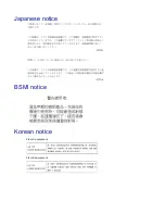
Page 24: ...Japanese notice BSMI notice Korean notice Class A equipment Class B equipment ...

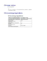
Page 25: ...Chinese notice Class A equipment China energyregulations ...

Page 26: ...ed in a manner that protects human health and the environment For more information about where you can drop off your waste equipment for recycling please contact your local city office your household waste disposal service or the shop where you purchased the product Power cord requirement The power cord should be approved for use in your country The power cord must be rated for the product and for...

Page 27: ...onent or assembly Grounding methodstopreventelectrostatic discharge Several methods are used for grounding Use one or more of the following methods when handling or installing electrostatic sensitive parts Use a wrist strap connected by a ground cord to a grounded workstation or computer chassis Wrist straps are flexible straps with a minimum of 1 megohm 10 percent resistance in the ground cords T...

Reviews: