background image


(17) 


 Starter Specifications 


16 H.P. 

24 H.P. 

Code No 

298783 

298876 

Type Solenoid 

actuated 

with 

overrunning clutch 

Nominal voltage 

12V 

Nominal output 

0.8 kW 

1.0 kW 

Direction of rotation 

Clockwise viewed from pinion end 


Trouble shooting 

If the battery turns extremely slow or not at all, the cause may 
lie in the battery, wiring or the starter The lights are a very 
convenient tool for tracing the cause of the trouble. 
Light method 
The use of this method, of course, assumes that the lights 
are functioning normally. 
(1)  Lights are dim 

Probable cause: Low battery. faulty contact at one of  

the connections, faulty wiring. If the battery remains 
discharged because of a malfunction in the charging 
system, it should be corrected before charging the 
battery to prevent the problem from reoccurring. 

(2)  With battery fully charged: 

a)  Symptom. Lights do not light 

Probable cause: Battery terminal not properly 
connected. 

b)  Symptom: Lights become extremely dim when 

cranking the engine and starter slows down or 
stops. 
Probable causes.  

Bad engine (rotational resistance too great) 
Starter does not turn satisfactorily 

Armature shaft bent 
Worn bushing 
Pole core screw loose 

Field coil grounded or insulator short circuited 
Armature coil grounded or insulator short-circuited 

c)  Lights are bright Out starter does not I urn or hums 

very slowly. 
Probable causes. 

Starter terminal not connected properly 
Solenoid switch not making contact 
Solenoid not working (coil grounded or insulator short-
circuited) 
Faulty starter switch contact 
Insufficient brush contact 
Dirty or worn commutator 


 Precautions in care and handling of starter motor


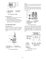
(1)  The starting motor must be installed properly for the 

starter pinion to mesh with the engine ring gear as 

should. If the ring gear and pinion do not mesh properly, 
the pinion and starter housing may be damaged and in 
extreme cases, the starter may not even turn. 

(2)  If the starter switch is turned on and the engine turns, 

but will not start, the cause is probably in the fuel 
system. Check the fuel lines and correct as necessary. 

(3)  In attempting to start an engine, never use the starting 

motor for more than 30 seconds at a time without a 
pause to let is cool down. The starting motor heats up 
very rapidly when used and if it is used continuously for 
more than 30 seconds the solder may melt from the 
armature or the coil or lead wires may melt. Also, the 
battery will be discharged to such a degree and wont 
have sufficient power for another attempt at starting. A 
good rule to follow is to crank for 10 seconds and pause 
for 10 seconds. Repeat until the engine starts. 

(4) 

If the starting motor is too far forward, the pinion will not 
mesh properly with the ring gear and cause rapid pinion 
wear. Adjust for proper mesh. 

(5)  Do not turn the starter switch while the engine is 

running. If this is done, the pinion gear will contact the 
ring gear, which is turning with the full force of the 
engine which may cause a broken pinion, bent shaft, 
broken housing, etc. 


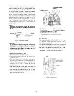
 Glow Plugs 

The glow plugs are shown in Fig. 44. 


Summary of Contents for Universal diesel 5416

Page 1: ...rs Universal Motors This copy of the Universal Motors Service Manual has been re created using images computer scanned from a manual rather than original artwork Note that where the page breaks appear...

Page 2: ...ystem 7 Valve Timing 8 Compression Release 9 Cylinder Liner 10 Cylinder Head 10 Piston Rings 11 Crankshaft 11 Connecting Rod 12 Gear Train 13 Camshaft Bearings 13 Main Bearings 14 Injection Pump 15 Wa...

Page 3: ...Electric Electric Mechanical Electric 2 2 Qts 3 7 Qts 5 6 Qts 11 5 Qts 8 5 Qts Lubrication Engine Use SAE 30 HD CD or 10W40 heavy duty diesel lubricating oil Lubrication Transm n Fill to mark on dipst...

Page 4: ...e Rotation Clockwise when viewed from V belt end Propeller Rotation Right Hand Both Standard V Drive Engine Weight Pounds 245 365 425 490 545 Length Overall 25 6 28 0 32 5 36 2 36 0 Height Overall 21...

Page 5: ...itions it should only have to be replaced every 400 hours To install apply a small amount of fuel to the packing and tighten securely by hand For removal the use of a filter wrench 15221 86611 is reco...

Page 6: ...outdoors are always considered to contain water so always filter this fuel before using Clean fuel is a must as the fuel is forced through parts of the pump and nozzle with clearances of 0 0004 in 1 1...

Page 7: ...d be done in fresh clean fuel 2 The nozzle should always be installed as an assembly never by component parts 3 Remember never to let the nozzle spray contact unprotected flesh 4 Tighten the retaining...

Page 8: ...ower than normal r Oil Filter 1 Replace the oil filter at every other oil change every 150 hours 2 Under normal conditions it is only necessary to change the oil filter at specified intervals If howev...

Page 9: ...ployed to preheat the fuel for easy starts down to 50 F 150 C Valve Combustion air of course is brought in through the intake valve when the descending piston creates a partial vacuum in the cylinder...

Page 10: ...n Fig 17 the standard valve timing shown in the chart can be attained Rocker Arms Intake valve opens 20o B TDC Intake valve closes 45o A TDC Exhaust valve opens 50o B TDC Exhaust valve closes 15o A TD...

Page 11: ...ile the engine is running reduce the speed to idle before doing so Adjustment of compression release 1 Set exhaust valve in totally closed position 2 Remove decompression adjustment window cover from...

Page 12: ...ndard size piston must again be used Tightening Cylinder Head Capscrews Fig 23 1 The tightening torque of the cylinder head capscrews is 54 to 58 ft lbs 7 5 to 8 0 kg m Numbers 7 8 11 and 13 are studs...

Page 13: ...en installing the undersize bearings observe the fol lowing precautions a Machine the crankpin diameter and radii to within a few thousandths of the correct dimensions and finish grind to the exact di...

Page 14: ...kpin Diameter Metal Mark Running Clearance in mm 020 0 20 mm undersize 1 7228 to 1 7234 in 43 759 to 43 775 mm 020 US 040 0 40 mm undersize 1 7149 to 1 7156 in 43 559 to 43 575 mm 040 US 0 001379 to 0...

Page 15: ...efer to Fig 31 Place the camshaft retainer plate on the camshaft first Shim the camshaft retainer plate out from the camshaft 0 003 to 0 009 in 0 07 to 0 22 mm with shims that can be pulled out after...

Page 16: ...ngs in engine block Slide the crankshaft assembly into the engine block being careful not to nick or scrape the crankpins After the assembly is in position make sure the oil passages are correctly lin...

Page 17: ...1 to 0 002 in 0 020 to 0 054 mm and 0 008 to 0 020 in 0 20 to 0 51 mm end play Injection pump camshaft Injection pump camshaft Fig 37 Install the bearings and governor unit on the camshaft and install...

Page 18: ...r pulley and the crankshaft pulley is 026 to 0 35in 7 to 9 mm with a force of 20 lbs applied Proper belt tension is essential for good engine cooling and belt life See Fig 38 Starting Motor The starti...

Page 19: ...ontact Solenoid not working coil grounded or insulator short circuited Faulty starter switch contact Insufficient brush contact Dirty or worn commutator Precautions in care and handling of starter mot...

Page 20: ...use hard starting and various other problems 2 As the glow plugs are in parallel the controller heating element will turn red even if one of the plugs is bad However the time it takes for the controll...

Page 21: ...19...
Page 22: ...rference Clearance 0 0004 in 0 0004 in 0 011mm 0 011mm 0 9071 in 23 04 mm Oversize 0 020 in 0 5 mm Piston Ring Ring gap Top ring width 2nd ring width Oil ring width top 2nd oil ring Keystone type 0 07...

Page 23: ...kshaft metal 1 width Crankshaft metal 1 OD 2 0441 2 0449 in 51 921 51 94 mm 2 0465 2 0488 in 51 98 52 039 mm 0 7823 0 7925 in 19 87 20 13 mm 2 2485 2 2474 in 57 111 57 084 mm Running clearance 0 0016...

Page 24: ...alve clearance 0 0433 0 0551in 1 1 1 4 mm 45o 1 2953 1 3031in 32 9 33 1 mm 1 0591 1 0669in 26 9 27 1 mm 0 3134 0 3140in 7 960 7 975 mm 0 3156 0 3161in 8 015 8 030 mm 0 0016 0 0028in 0 04 0 07 mm 0 007...

Page 25: ...5874 in 14 90 14 92 mm 0 8622 0 8630 in 21 90 21 92 mm 1 9669 1 9685 in 49 96 50 00 mm 0 0035 0 0063 in 0 09 0 16 mm 0 0039 0 0059 in 0 10 0 15 mm 64 71 psi 4 5 5 kgf cm2 4 2 gal min 16 min 5 8 gal mi...

Page 26: ...mm HM 41 50in 1054 mm 0 0232 0 437 in 0 59 1 11 mm Packing thickness 26 4 gal min 100 min or more 12 8 psi 0 9 kgf cm2 In perimeter In perimeter With pressurized radiator corrugated Water temperature...

Page 27: ...Rod bolts M10 x 1 25 M12 x 1 25 M10 x 1 25 M8 x 1 25 M8 x 1 25 M8 x 1 54 2 57 9 ft lbs 7 5 8 kgf m 72 3 79 6 ft lbs 10 11 kgf m 47 0 50 6 ft lbs 6 5 7 kgf m 21 7 25 3 ft lbs 3 3 5 kgf m 17 4 20 3 ft l...

Page 28: ...numbers punched on the bolt heads Prior to tightening be sure to check out the numbers as shown below Punched Number Bolt Material Grade None Standard Bolts SS41 S20C 7 Special Bolts S43C S48C Refine...

Reviews: